crystal - Replacing a Control Surface Module
This topic describes how to exchange a crystal control surface module. The same instructions can be applied to a Fader or Main module. In the example below, a Fader module is shown.
If you need to exchange a VX module, then this can be done using the instructions in crystal - Mounting a VX Module.
Overview
The control surface module is held in place by six screws that fix to the frame housing:
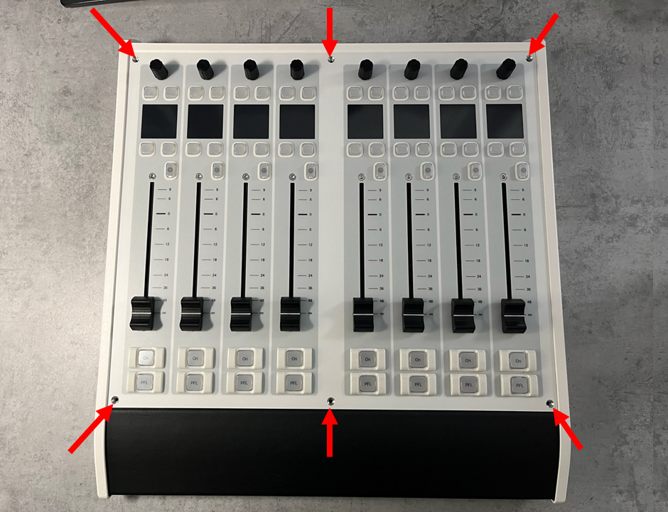 crystal Fader Module | 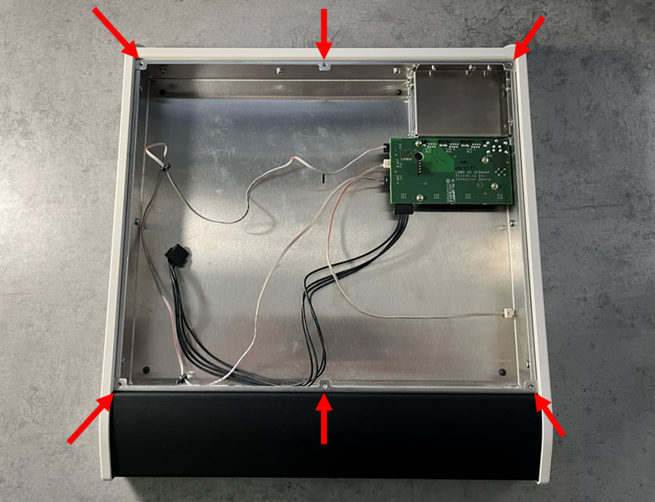 crystal Frame (with module removed) |
Internally, the module connects to the frame's connector board using three wired connectors (1x power and 2x CAN) and a plugin connector (1x ETHERNET).
The image below shows the connector board components.
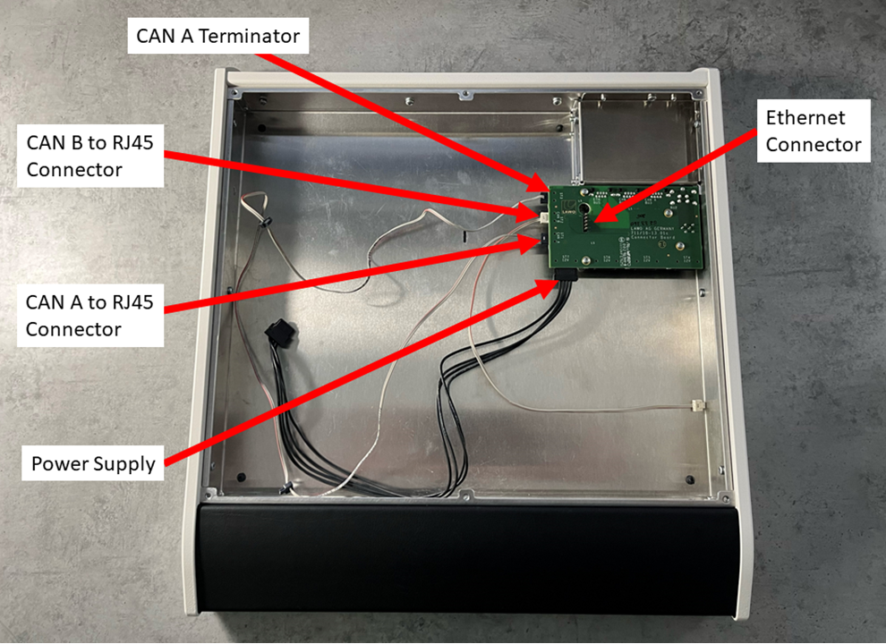
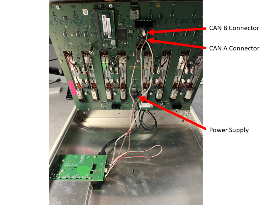
The image below shows the connections from the module to the connector board. In this view, the surface is rotated by 180 degrees and the module is lifted.
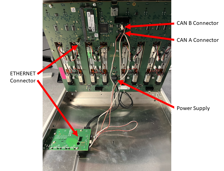
To exchange a module, you must loosen the fixing screw(s), lift the module and unplug the connectors. Then fit the replacement module in the reverse order.
What you will need
- 1 x Torx10 driver.
- 1 x replacement module, either Fader or Main (any type) - ordered using the part numbers listed here.
Instructions
Please read the following important safety information and then follow the step-by-step instructions.
![]() (E) WARNING
(E) WARNING
Please read and observe ALL of the Lawo - Important Safety Instructions BEFORE installing or servicing any component.
![]() (F) AVERTISSEMENT
(F) AVERTISSEMENT
Veuillez lire et respecter TOUTES les consignes de sécurité importantes AVANT d’installer ou d’entretenir un composant.
![]() (E) CAUTION
(E) CAUTION
For safety reasons, the frame must be populated with either a Fader or Main module (and not operated with an empty slot).
1. Power off and disconnect the surface.
- To power off, turn off the mains input to the external power supply.
- Then remove all cables from the connector board (at the rear of the frame).
- If the frame is fitted with a VX module, then this does not need to be removed, but should be powered off (by turning off the mains input to the VX power supply).
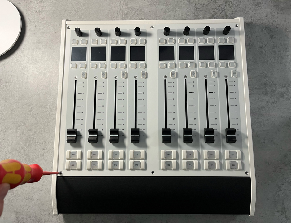
2. Remove the screws that secure the module to the frame.
- There are 6 screws positioned along the top and bottom edges of the module: M3 x 5mm.
- You should use a Torx T10 driver for this purpose.
- Take care to store the screws safely.
 |  |
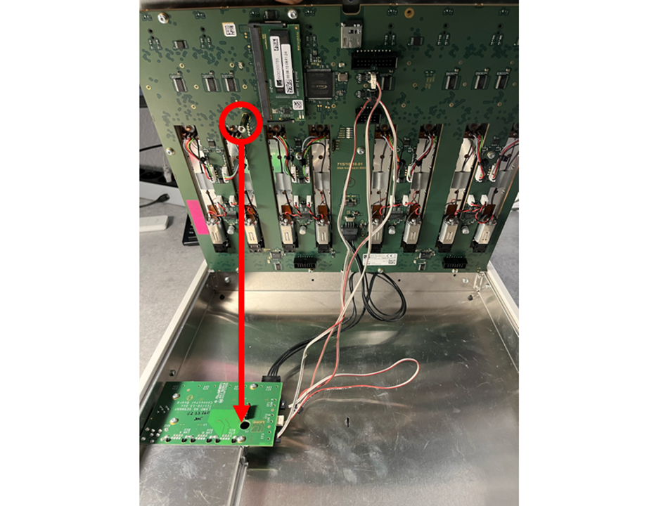
3. From behind the frame, carefully lift the module (to reveal the connectors).
- You can use the rotary controls to help get a good grip.
- Take care not to crush any of the cables.
- The screw beside the Ethernet connector should slide out of the hole in the frame's connector board (to release the plugin connector).
4. Disconnect the module's connectors.
- There are three internal connector to unplug: 1x power and 2x CAN bus.
- For the CAN bus, take note of which cables are for CAN A and CAN B.
5. Remove the module from the frame.
- Carefully remove the module by lifting it out of the frame.
- Lay the module face-down on a piece of foam, or similar ESD-proof protective material, away from the console.
6. Fit the replacement module in the reverse order.
- Take the new module out of its packaging and lay it down on a piece of foam, or similar ESD-proof protective material, beside the console.
- Taking care not to crush the cables, position the module in the frame.
- From the rear, lift the module and plug in the wired connectors: 1x power and 2x CAN bus.
- Carefully lower the module into position.
Important: It is important that the screw beside the Ethernet connector slots through the hole in the connector board (to ensure that the Ethernet connection is correctly made).
7. Replace all of the fixing screws and tighten them securely.
- Tightening the screws ensures that the module's Ethernet connection to the connector board is secure.
8. Reconnect the external cabling and test the operation.
- Connect the cables to the rear connector board.
- Turn on the mains input to the external power supply.
What happens next is explained in crystal - Powering On.