crystal - Mounting a VX Module
For Virtual Extension frames, the VX module is shipped separately. This must be mounted into the frame as described below.
The same principles apply to both tabletop and countersunk frames. All VX modules are identical and so they can be mounted in any order (if you have more than one crystal frame).
Overview
The VX module sits directly above the physical controls at a fixed viewing angle.
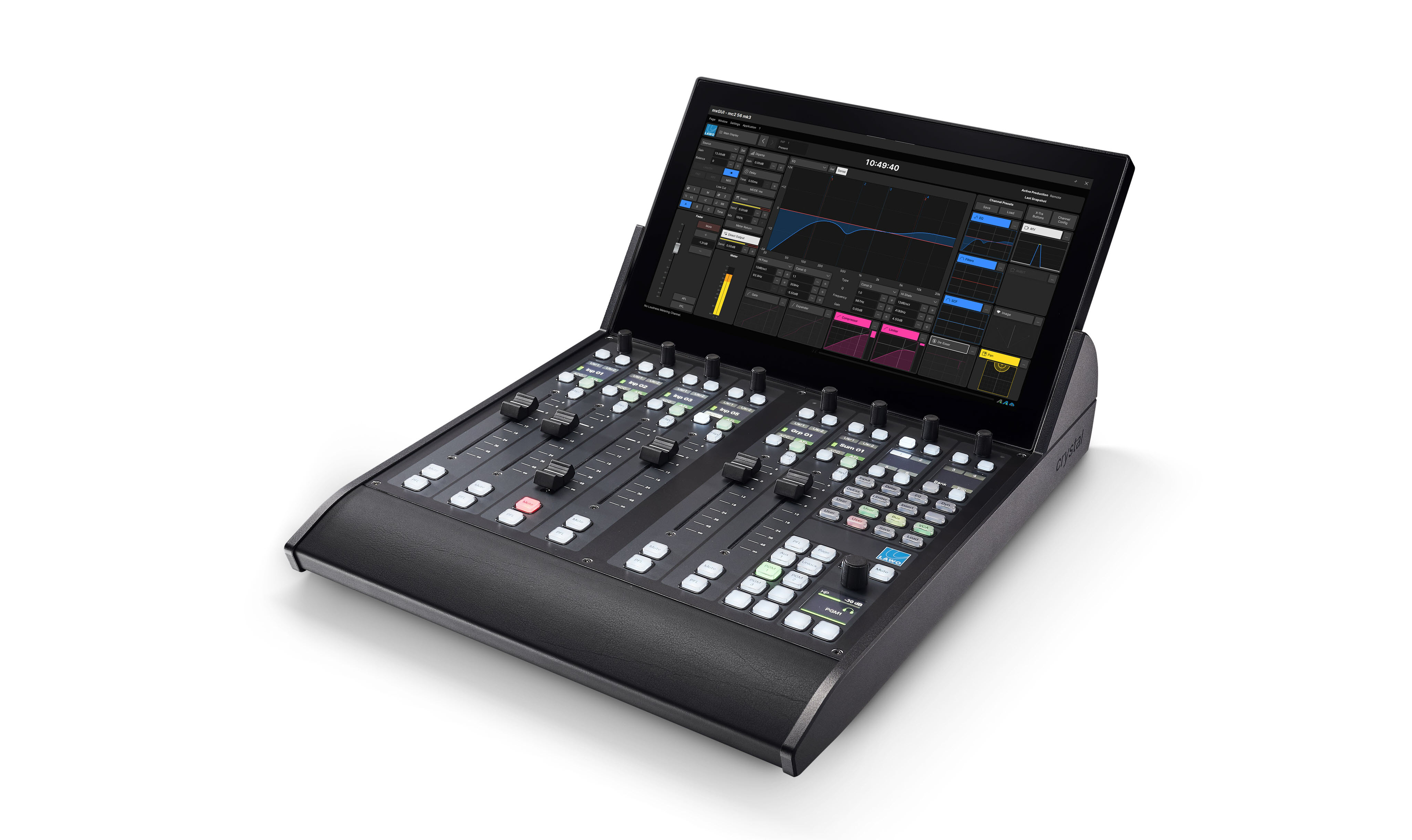
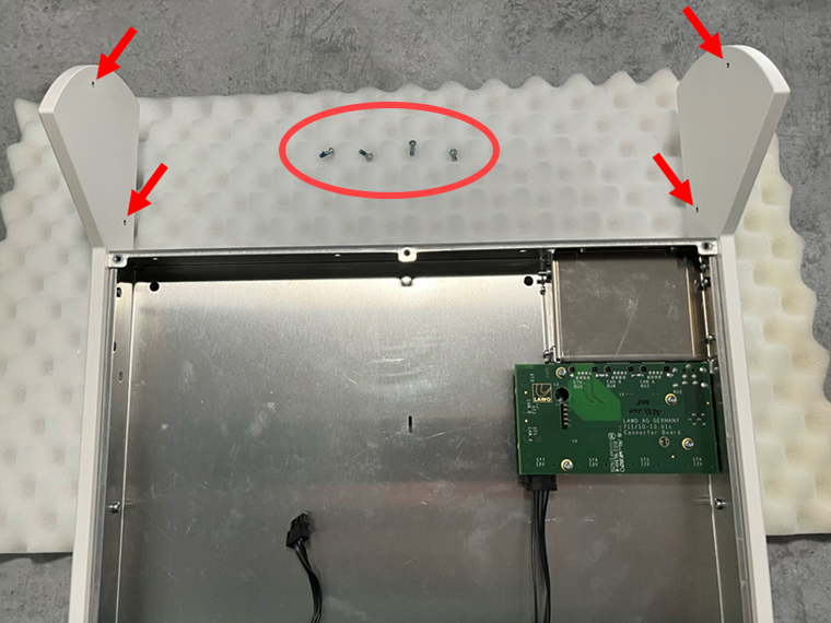
The VX frame comes with special side profiles that hold the VX module. Each profile includes two pre-drilled holes (for the screws that secure the module to the frame).
The image below shows the screw thread positions (from the front) in an empty frame. Note that, the frame is delivered with either a Fader or Main module fitted (and there is no need to remove the surface module).
To mount the VX module, you must place the crystal frame on one side. Slide in the VX module and secure the module to this side. Then turn over the frame and secure the opposite side.
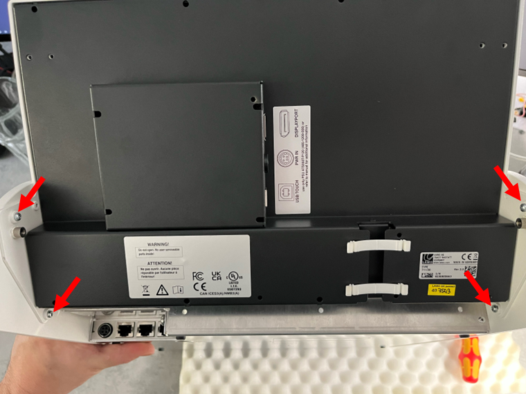
The image below shows the four mounting screws (from the rear) once the VX module is installed.
What you will need
- 1 x Torx10 driver.
- 1 x VX module (any type) - ordered using the part numbers listed here.
- 4 x VX module mounting screws (M3 x 8mm) - included with the VX module.
Instructions
1. Place the crystal frame on one side (either left or right is fine).
- To protect the surface finish, you should lay the frame on a piece of foam, or similar ESD-proof protective material.
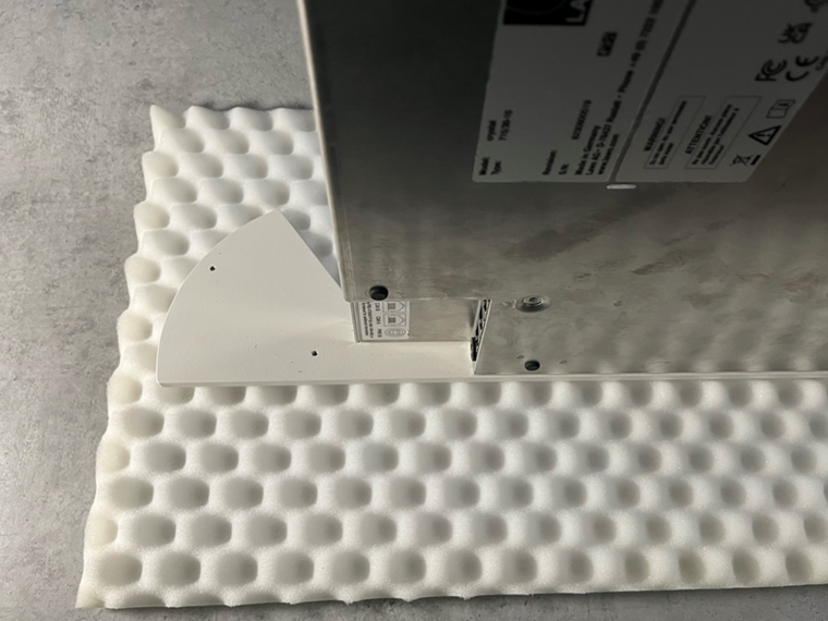
2. Slide the VX module into the frame.
- Take the VX module out of its packaging and lay it down on a piece of foam, or similar ESD-proof protective material, beside the console.
- Carefully slide the VX module into the frame, so that the screw holes (in the module) and threads (in the frame) align. It helps to use the lower thread as a guide.
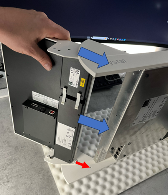
3. Secure the VX module to the frame.
- Carefully, fit the first pair of mounting screws (M3 x 8mm), taking care to check the alignment.
- Using a Torx10 driver, tighten the screws until the VX module feels secure.
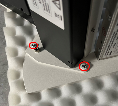
- Then lift and turn the frame onto its opposite side.
- Repeat the process using the second pair of mounting screws.
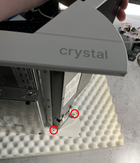
- Once all four screws are tightened, lift and turn the frame onto its underside (ready for mounting/cabling).
4. Check the mounting.
- If there is any looseness in the VX module, then tighten the four screws.
- This should be done before the frame is mounted in its final position.
- The screws can be accessed from the rear of the frame (as shown below) without needing to turn the frame onto its side.

Fitting the Cable Cover
Optionally, a cable cover can be fitted to protect the connections and make the rear of the console look nicer. The cable cover is not included and must be ordered separately.
The cable cover should be fitted once the VX module is connected and the system is fully tested.
There are four plastic pins that hold the cover in place. The image below shows the rear of a VX module with the cable cover fitted.