Lawo VSC - Audio Device Configuration
This topic provides more information about the audio devices in Lawo VSC.
New Audio Device - Configuration (Part 1)
The following fields are defined when you add a 'New Audio Device'.
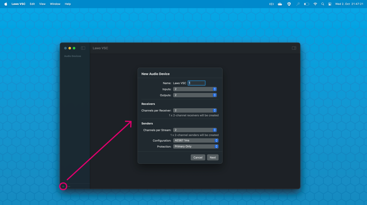
Name
The Name identifies the audio device in Lawo VSC and in the macOS.
- The name always starts with "Lawo VSC"; this cannot be changed. The second part of the name can be edited.
- Although the name does not have to be unique, this is strongly recommended so that the device is easy to identify.
Inputs and Outputs
The Inputs and Outputs define how many mono inputs and outputs the device can handle. i.e. the I/O capacity of the audio driver.
- Please enter a value that meets the requirements of the local audio application/driver.
- In each case, the drop-down menu offers the following values: 0, 1, 2, 4, 8, 16, 32, 64 or 128.
Please note: To configure more than 2 inputs or outputs, you must be running the licenced version of Lawo VSC. If you are running the free version, then the 'Upgrade License' dialog appears if you try to assign a higher value.
Channels per Receiver / Channels per Stream
Once the Inputs and Outputs are defined, you can enter the number of Channels per Receiver and Channels per Stream.
- Once a value is selected, Lawo VSC calculates the number of senders (or receivers) and displays this below the corresponding field.
- In each case, the drop-down menu offers the following values: 0, 1, 2, 4, 8, 16, 32, 64 or 128.
The Channels per Receiver sets the maximum number of channels that can be received. Once an incoming stream is connected, if there is a mismatch, then the incoming channels are received on a best-effort basis. For example:
- If a stereo stream is connected to an 8-channel receiver, then the two source channels are assigned to channels 1 and 2 of the receiver (and channels 3 to 8 of the receiver are unused).
- If a 64-channel stream is connected to an 8-channel receiver, then the first eight source channels are assigned to channels 1 to 8 of the receiver (and the remaining source channels from the incoming stream are unused).
The Channels per Stream defines the configuration of the outgoing stream(s). i.e. whether Lawo VSC creates a single multi-channel sender or splits the load into several smaller (2-channel) streams. The image below shows two possible configurations for an 8 in / 8 out device.
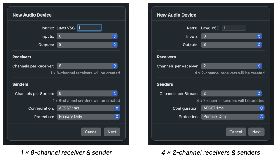
When defining the Channels per Stream, it is important to consider the network bandwidth (of the NICs and media network).
The resultant stream size is defined by the number of channels, codec type and frame size. This is important if network bandwidth is an issue. Thus, the network topology should be considered before defining the number of channels per stream.
If the value entered results in an invalid packet payload size, then the following message appears.
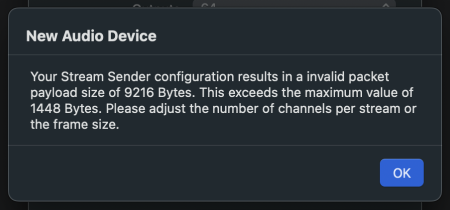
In this instance, select OK to clear the dialog. Then enter a different value for the Channels per Stream (or Frame Size). The Frame Size can be edited by defining a custom configuration (as described later).
Configuration
The Configuration defines the advanced parameters for the outgoing stream(s). There are two ways to define the parameters: either automatically (by selecting an AES67 preset) or manually (by selecting Custom).
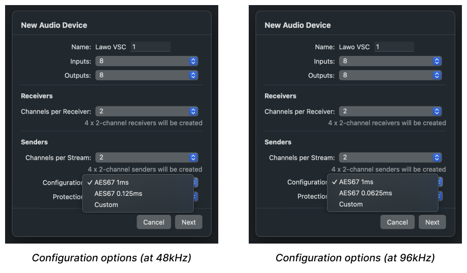
In most cases, it is recommended to accept the default preset (as this ensures that the streaming configuration is permitted, and that the streams are AES67-compliant). If you wish to change the streaming configuration, then choose an option from the drop-down menu (as shown below).
Please note:
- The available AES67 presets are dependent on the number of Channels per Stream (to ensure that the resultant stream size is always permitted). For example, the AES67 1ms preset is not available for a 64-channel sender (as the stream size would be too large).
- The presets are named differently depending on the sample rate of the streams. In each case, the time specified refers to the packet time (per channel) of the resultant streams.
- At 48kHz (or 44.1kHz), the options are: AES67 1ms, AES67 0.125ms or Custom.
- At 96kHz, the second option changes to AES67 0.0625ms.
Using the Presets (for AES67 Compliance)
To ensure that all outgoing streams are AES67-compliant, it is recommended to set the Configuration to one of the AES67 presets. The number of presets on offer are dependent on the number of channels per stream (to avoid an invalid packet payload size).
The packet time is included in the preset name to help you choose the correct option for your network. For example, the AES67 1ms preset delivers streams with a packet time of 1ms (per channel).
When operating at 48kHz, the packet time (and equivalent frame size) values are as follows:
- AES67 1ms = 48 samples (per channel).
- AES67 0.125ms = 6 samples (per channel).
At 96kHz, this changes to:
- AES67 1ms = 96 samples (per channel).
- AES67 0.0625ms = 6 samples (per channel).
If you choose a shorter packet time (smaller frame size), then the device transmits its packets more frequently. This results in a lower sending latency, but also a higher demand on the network's bandwidth.
In each case, the remaining parameters are set to the following values:
- Codec = L24
- RTP Payload Type = 98
- TTL = 16
- Mode = Multicast
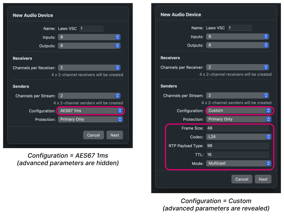
The example below shows how the configuration looks if you choose the AES67 1ms preset and then switch to Custom mode.
Custom Configuration
When the Configuration is set to Custom, the advanced parameters are revealed: Frame Size, Codec, RTP Payload Type, TTL and Mode (Muticast or Unicast). This makes it possible to define the streaming configuration manually.
The advanced parameters can be edited in the same manner as for other Lawo streaming devices. For more information, please see Lawo VSC - Sender Parameters.
For now, it is useful to know that:
- In Custom mode, each parameter can be set to any possible value. This means that the resultant streams may not be AES67-compliant.
- If an invalid combination of Channels per Stream, Codec and Frame Size, then the "invalid packet payload size" warning message appears (as described earlier).
- You can reset the parameter values by returning the Configuration to one of the AES67 presets.
Protection
The Protection field defines the network interface(s) used to transmit the streams.
- By default, Primary Only is selected (to be compatible with the free version of Lawo VSC).
- To create redundant streams, compatible with SMPTE ST2022-7, you must change this option to Dual Redundant.
Please note: To support the Dual Redundant protection mode, you must upgrade to the licensed version of Lawo VSC. Then, assign a secondary streaming interface using the NIC 2 field in the 'Settings → Streaming' dialog.
New Audio Device - Configuration (Part 2)
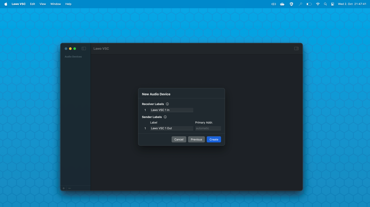
At the next screen, you are asked to label the receivers and senders, and define a multicast IP address and port number for each of the outgoing streams.
Receiver and Sender Labels
To save time, it is recommended to use the default labels. These start with the device name (entered earlier).
If there is more than one receiver or sender, then the labels end in a number that increments automatically. Thus, the default labels are:
- <device name> In n - for receivers.
- <device name> Out n - for senders.
The default labels can be overwritten by typing into the fields.
Each label must not exceed 28 characters.
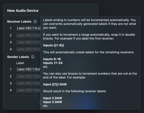
To speed up the labelling for multiple receivers or senders, double braces can be used to automatically increment a number or range. Click on the i icon to open an "information" dialog that explains how to use this shortcut.
Sender Multicast IP Addresses & UDP Port Number
Beside the sender labels, the Primary Addr. field determines how the multicast IP addresses are created. There are two possibilities: either automatic or manual.
If you leave the field empty, then the stream will be allocated an automatic multicast IP address. In this instance:
- The pattern used to generate the multicast IP addresses can be edited from the 'Settings → Streaming' dialog.
- You can check the allocated address once the stream is created by opening the SDP data for the stream.
If your network supports a limited IP range, then you may wish to assign a multicast IP address manually. In this instance, type the required values into the corresponding fields.
Please note: The Protection option (defined earlier) determines how many address fields are visible. For example:
- If the Protection is set to Dual Redundant, then both the Primary Addr. and Secondary Addr. must be defined.
- If the Protection is set to Primary Only or Secondary Only, then only one address is required.
By default, the UDP port number for all streams is set to 5004. This can be edited on a per stream basis by turning on the Enable definable port per stream option (in the 'Settings → Advanced' dialog).
Once enabled, the Port field becomes visible (as shown below).

This can be used to enter a port number for each individual stream. If nothing is entered, then "automatic" is displayed and the default port number (5004) is used.