App Server - Advanced -> PTP
The Advanced → PTP menu provides controls relating to the synchronization of the App Server to Precision Time Protocol (PTP).
There is a main page and two sub-pages:
Key points to check are:
- The Clock Status (in the main PTP page) should show as Locked.
- The PTP → Network Interfaces (sub-page) selects the network interfaces, in the App Server, that are expecting to receive PTP.
- The PTP → PTP Configuration (sub-page) is where you can set and adjust PTP parameters, including domain, announce and sync intervals, delay request intervals, and unicast mode. Options like TAI offset and hybrid mode can also be enabled or adjusted, ensuring precise synchronization for your system.
- Comprehensive metrics about the PTP synchronization can be monitored using the PTP Clock Synchronization Grafana Dashboard. This can be easily reached by clicking on the Dashboard link at the bottom of the main PTP page.
Before making any changes to the PTP Configuration, it is important to understand that:
- Each App Server acts as a PTP slave only. This means that a PTP master clock source must be installed somewhere on the network, either by configuring another streaming node or installing a separate grandmaster device.
- The PTP master should be capable of taking an incoming sync signal and generating PTP clock. You can read more about the PTP implementation in the Lawo IP Networking Guide.
- At any moment in time, there can be only one PTP master operating on the network. If a device is set to master-slave mode, then the current mode is determined by the PTP priorities set within the device itself and all other streaming nodes.
PTP
The main page displays information about the PTP synchronization.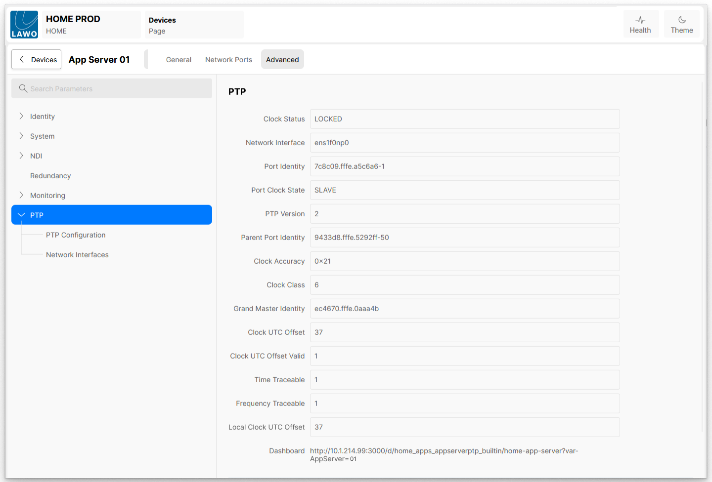
Clock Status
Displays the current status of the PTP locking process:
- Locked - The system clock is locked to a PTP source. When the system clock is within +/- xxx ns of the master clock, the clocks are considered 'Locked'. Only fine adjustments are being applied to maintain synchronisation.
- Locking - A valid PTP source has been detected, the process of locking the system clocks to PTP has begun.
The Clock Status may occasionally transition from Locked to Locking. This indicates that the offset between system clocks and the master clock is in excess of xxx ns.
This can sometimes occur when network traffic is temporarily delayed, due to a congested network, for example. Often this is not necessarily a problem, as the system clock will continue free-running until a Locked state is re-established. - Not Locked - A valid PTP source has been detected, but the locking process has started. Large adjustments are being applied.
- Waiting - A PTP source has not yet been discovered, the PTP locking process has not yet started.
Network Interface
Displays the name of the Network Interface in the App Server which is providing the PTP source to the App Server.
Port Identity
The unique PTP identity assigned to the PTP slave device (App Server)
Port Clock State
Describes the App Server's current function within the configured PTP domain:
- Slave - The port is receiving PTP synchronisation messages and is adjusting its clock to match the master.
- Uncalibrated - A temporary state where the port has detected one or more masters but is still in the process of selecting a master to synchronise with.
PTP Version
Displays the PTP protocol version in use. This should display a value of '2'. PTP Version 2 is also known as IEEE1588-2008.
Parent Port Identify
The unique PTP identity of clock that the PTP slave device (App Server) is synchronising with, as determined by the BMCA (Best Master Clock Algorithm)
Clock Accuracy
Displays the Clock Accuracy parameter, an indicator of clock quality, as advertised by the PTP Grandmaster
For example, '0x21' means < 100ns, '0x23' means < 1ns.
Clock Class
Displays the Clock Class parameter, an indicator of clock quality, as advertised by PTP Grandmaster
For example, '6' means the device has a primary time reference source, such as GPS. '7' means the device used to have a primary time reference source.
Grand Master Identity
The unique PTP identity of the PTP grandmaster
Clock UTC Offset
Displays the current offset between PTP and UTC reported by the PTP Grandmaster.
The PTP UTC clock offset is currently 37 seconds, representing the difference between International Atomic Time (TAI) and Coordinated Universal Time (UTC), due to the way leap seconds are applied to TAI to keep it aligned with Earth's rotation.
PTP systems typically distribute TAI timestamps, so the 37-second offset is a value that must be known to convert TAI to UTC. The offset is included in PTP Announce messages and changes when a new leap second is added to UTC.
Clock UTC Offset Valid
Displays the current UTC Offset Valid flag reported by the PTP Grandmaster.
The UTC Offset Valid flag (UTCV) signals to slave nodes that the current offset value between TAI and UTC, provided in Announce messages, is verified and safe to apply.
Time Traceable
Indicates whether the Grandmaster is connected to a primary time reference source, such as GPS or an atomic clock, and thus its timescale and UTC offset is traceable to international standards.
Frequency Traceable
Indicates whether the Grandmaster is connected to a primary time reference source, such as GPS or an atomic clock, and thus the frequency that defines its timescale is traceable to international standards.
Local Clock UTC Offset
Displays the actual TAI offset being used on the server.
This could be different to the Clock UTC Offset reported by the PTP Grandmaster if:
- the offset has been overridden by the App Server's PTP Configuration controls (described below).
- the Grandmaster clock is not setting the Clock UTC Offset Valid flag.
- the Grandmaster clock is not traceable.
If either of the last two are true, then the App Server ignores the offset advertised by the Grandmaster.
Dashboard
This is a link which, when clicked, will redirect the browser to a Grafana Dashboard showing PTP information regarding the App Server. For more information, please see Performance Monitoring (using Grafana Dashboards).
PTP → PTP Configuration
The PTP Configuration sub-page provides controls relating to the App Server's PTP configuration.

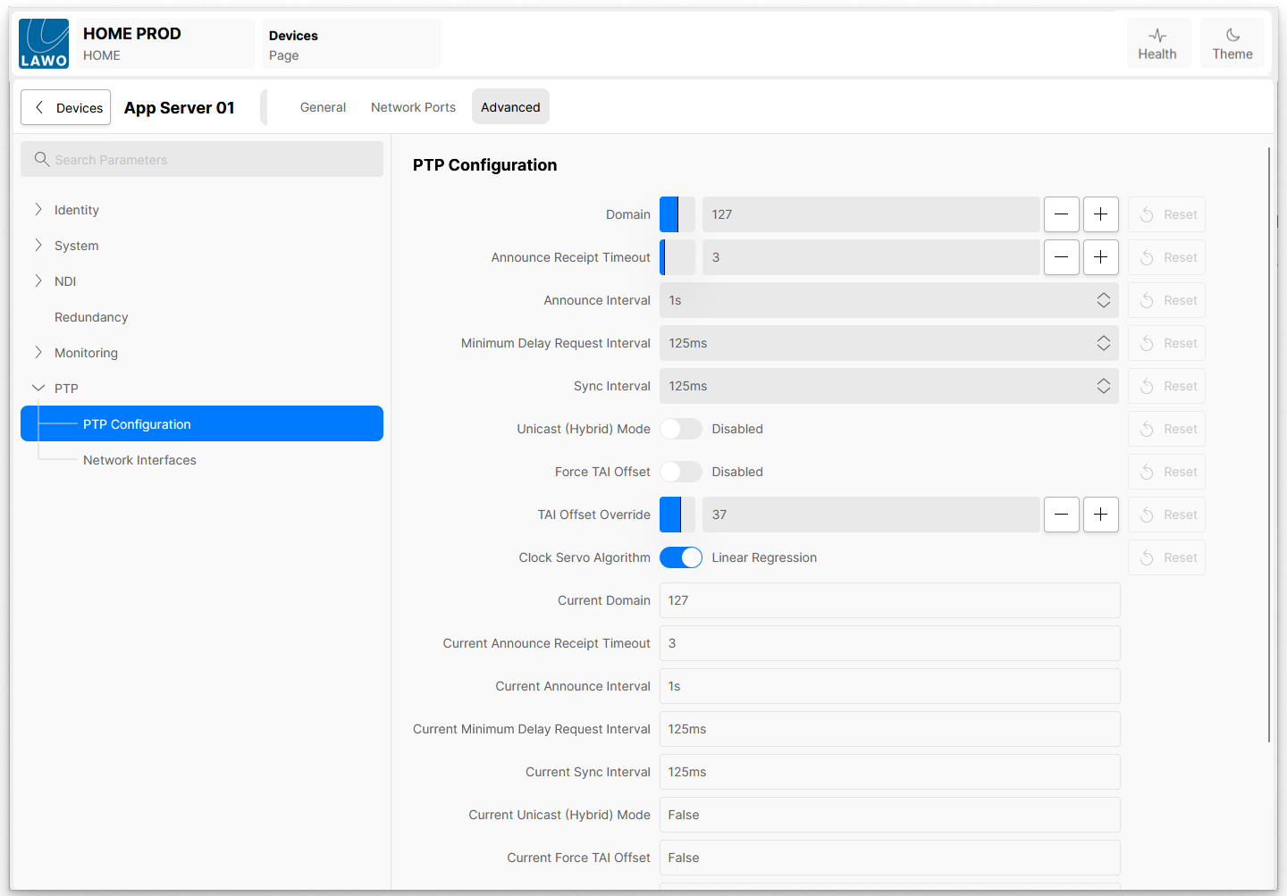
Domain
Allows the user to define which PTP Domain the App Server belongs to. Changes to this control will only take effect once the Apply Settings - Trigger Event button is pressed.
Multiple PTP domains can be defined in any given network, which could be considered as logically isolated PTP subnetworks; each will have its own grandmaster clock. This approach offers a level of redundancy, a failure in any one PTP subnetwork will only affect that PTP domain.
Announce Receipt Timeout
Allows the user to define the Announce Receipt Timeout value. Changes to this control will only take effect once the Apply Settings - Trigger Event button is pressed.
The Announce Receipt Timeout value defines how many Announce messages an interface can fail to receive before Best Master Clock Algorithm considers the master device lost.
Announce Interval
Allows the user to define the Announce Interval value. Changes to this control will only take effect once the Apply Settings - Trigger Event button is pressed.
The Announce Interval value defines how often a PTP device sends Announce messages to its network peers, with the interval measured in 'log seconds'.
Minimum Delay Request Interval
Allows the user to define the Minimum Delay Request Interval. Changes to this control will only take effect once the Apply Settings - Trigger Event button is pressed.
The minimal Delay Request Interval is the shortest time allowed between a PTP Slave device (the App Server) sending a Delay_Req message and the master sending a corresponding Delay_Resp message. The Minimum Delay Request Interval is measured in 'log seconds'.
Sync Interval
Allows the user to define the Sync Interval value. Changes to this control will only take effect once the Apply Settings - Trigger Event button is pressed.
The Sync Interval defines the rate at which PTP devices send Sync messages to synchronise time across a network. The Sync Interval is measured in 'log seconds'.
Unicast (Hybrid) Mode
Allows the user to enable or disable PTP working in Unicast (Hybrid) mode. Changes to this control will only take effect once the Apply Settings - Trigger Event button is pressed.
PTP Unicast (Hybrid) Mode is a communication mode where the PTP Master clock sends multicast Sync, Follow_Up and Announce messages, but PTP slave clocks send unicast Delay_Req messages and the master replies with unicast Delay_Resp messages. This mode provides a balance, allowing the master to broadcast general synchronisation information to all potential clients while still enabling slaves to perform two-way delay measurements with their specific master using unicast communication.
Force TAI Offset
Allows the user to enable or disable using a custom TAI offset, where the custom offset is defined in the TAI Offset Override control. Changes to this control will only take effect once the Apply Settings - Trigger Event button is pressed.
Under normal conditions in a properly configured PTP network, this control should remain disabled. Forcing or overriding the TAI offset with a customer value is highly likely to cause disruption of media flows to receivers further along the data path as timestamps within packets of media data will be affected.
In a properly designed system, the TAI offset is provided by the PTP grandmaster. PTP time (unlike UTC time) does not account for leap seconds. The TAI offset defines the difference between PTP time and UTC time, which at time of writing is 37 seconds.
The App Server TAI offset override controls are only for systems that do not have a proper grandmaster clock, and therefore the app server doesn't get told a TAI offset. This will be the case if (for example), the GM doesn't have GPS so is not considered 'time traceable' or 'frequency traceable'.
TAI Offset Override
Used in conjunction with the Force TAI Offset control. The value in this control defines the custom TAI offset (PTP time vs UTC time) to be applied. Changes to this control will only take effect if the Force TAI Offset control is enabled and once the Apply Settings - Trigger Event button is pressed.
Current Domain, Announce Receipt Timeout, etc.
The following fields provide information about the current status:
- Current Domain - Displays the current active PTP Domain configuration.
- Current Announce Receipt Timeout - Displays the current active PTP Announce Receipt Timeout configuration.
- Current Announce Interval - Displays the current active PTP Announce Interval configuration.
- Current Minimum Delay Request Interval - Displays the current active PTP Minimum Delay Request Interval configuration.
- Current Sync Interval - Displays the current active PTP Sync Interval configuration.
- Current Unicast (Hybrid) Mode - Displays whether Unicast (Hybrid) mode is currently enabled or not.
- Current Force TAI Offset - Displays whether a customer TAI Offset is being applied or not.
- Current TAI Offset Override - Displays the TAI Offset that will be applied if Force TAI Offset is enabled.
Apply Settings - Trigger Event
Applies any configuration changes when pressed.
PTP → Network Interfaces
The Network Interfaces sub-page allows the user to select which network interfaces, in the App Server, should be used to synchronise to PTP.
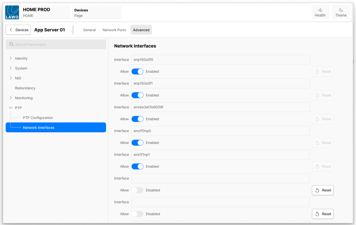
This page lists the first eight network interfaces, as detected by the operating system installed on the App Server.
In general, only high-speed (100G, for example) network interfaces should be considered for PTP synchronisation as they provide a much higher level of accuracy when compared to lower-speed (1G, for example) interfaces.
For each interface, there are two available controls:
- Interface - Displays the operating system's name for the network interface.
- Allow - When enabled, this network interface can be used to receive PTP information and facilitate time synchronisation with a master clock.