mc²96 - Control Surface Overview
The mc²96 control surface is available in a range of frame sizes that scale from 24 to 120 faders (with the dual-fader option and Xtra main faders).
The smallest frame size (16F+8C) includes one channel bay and the centre section. This can be expanded by adding one or more channel bays, fitted with either 16 (single) or 32 (dual) faders.
Front Panel Controls
All frames have an identical set of controls apart from the options for the channel bay panels (2), main faders (5) and user panels (6b).
The Channel Display provides visual feedback and touch-screen operation for the channels assigned to the fader strips. The first (lower) metering row is always present and shows information about the current bank and layer. The second and third rows are optional, and can show either the flip layer (of the current bank) or a specific bank and layer. Operators can make changes by touching the screen - for example, to edit the VCA and bus assignments or assign a different channel to the fader strip.
The channel fader strips provide dedicated mixing controls for the channels on the current bank/layer. Each bay can be fitted with either a single or dual-fader panel. The differences in operation are described below.
All faders and rotary controls are touch-sensitive, and are clearly labelled by the panel's displays. Any fader strip can control any type of channel and supports six banks, each with two layers. This allows you to control inputs and masters from any fader position, and handle lots of signals from very few physical faders.
The Central GUI (Graphical User Interface) is a high resolution touch-screen display that sits above the centre section controls. It is used to set up the console, and provide visual feedback and metering for the channel in access.
A few of the elements are visible at all times, while the main area can be paged through different displays. To change page, there are three possible methods: press a SCREEN CONTROL button in the centre section (7); touch the on-screen page menu; or use a keyboard shortcut. In the example above, the Main Display is open (to access all available parameters for the selected channel).
The Central Control Section provides parameter control for the selected channel (also known as the "channel in access"). From here you can adjust any channel parameter: input gain, EQ, Compressor, Aux sends, Panning, etc.
Start by pressing a fader strip SEL button (2) to select a channel. Then use the Central Control Section (4) to adjust the parameters. The rotary controls are touch-sensitive, and are clearly labelled by the panel's displays.
The main fader strips are identical to the channel fader strips (2), except that they do not have any upper (rotary) controls or a dedicated Channel Display. As standard, the console comes with 8 main faders, but this can be increased to 16 (by specifying the Xtra main faders option).
The main faders can be used for any type of channel: inputs or masters. To adjust parameters such as input gain or EQ, press a fader SEL button and use the Central Control Section (4). For touch-screen operation and metering, open the Main Faders display (on the Central GUI).
The space beside the Central GUI is fitted with an RTW TM9 (as standard) or a full-height blanking panel.
The space to the left of the MONITORING panel can be fitted with up to two Lawo user panels. If the centre section is fitted with the Xtra main faders option, then the lower slot must be used for the XTRA USER PANEL. In all other cases, the two slots are freely configurable. The available options are described below. Unless otherwise specified, the console ships with two blanking panels.
The centre section provides master controls and navigation for the Central GUI. There are two possible layouts to support either 8 or 16 main fader strips. In each case, the panel is divided into clearly-defined control areas. The SCREEN CONTROL page buttons, soft keys and trackball operate in conjunction with the Central GUI (3).
The following connections can be found on the underside of the front buffer (beneath the trackball).
1 x ETH A Network Port - connects to the control surface internal network (for diagnostics and setup).
4 x USB 2.0 Ports - the first three ports connect to the mc2 control system. They can be used to connect a USB memory stick (to save and load user data). The USB port marked RTW connects to the TM7 or TM9 meter (if fitted). This can be used for RTW diagnostics (as described in the RTW user manual).
1 x Stereo Phones - can be used to connect a pair of stereo headphones for the main engineer. By default, this follows the CRM 1 monitor source selector.
A second stereo phones socket can be found further along the front buffer. By default, this follows the CRM 2 monitor source selector making it ideal for a second engineer.
The console keyboard (and trackpad) are located on a pull-out drawer beneath the main faders.
The keyboard is available in one of two layouts: either English (default) or German. The matching version must be selected using the Global → System → Keyboard Layout option (in the System Settings display).
Control Surface Options
There are four main options that affect how the surface looks and operates: the channel bay panels (either single or dual-fader); the centre section (either 8 or 16 main faders); the user panels and overbridge metering.
Channel Bays: Single or Dual-Fader
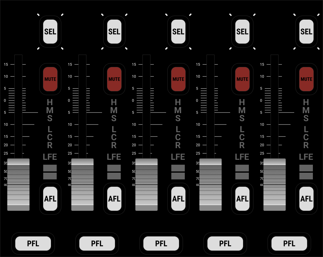
As standard, each channel bay comes with a single large-scale fader and six assignable Free Controls.
Optionally, the standard FC panel can be replaced with an "upper" fader panel to double the number of physical faders. This option provides 16 small-scale fader strips at the expense of four of the Free Controls. The upper fader always controls the alternate layer (for the selected bank); press FLIP (beside the lower fader) to reverse the assignments. The upper fader comes with four user buttons, a fader strip SEL button, MUTE plus AFL and PFL monitoring. In all other respects, the controls are identical to the single fader bay.
Either panel type can be fitted to individual channel bays as required, and can be retrofitted to an existing console. The image below shows the two channel bay options for comparison.
Centre Section: Standard or Xtra Main Faders
Optionally, the centre section can be fitted with a different lower central panel to increase the number of main faders from 8 to 16.
To support this option, the lower user panel slot must be fitted with the XTRA USER PANEL (to accommodate the master controls).
The Xtra main faders option can be retrofitted to existing consoles.
The image below compares the two layouts.
The configurations support the same functionality with a few operational differences. The table below describes the similarities and differences.
| Function | Location on Xtra Main Faders Console | Differences from Standard Console | |
|---|---|---|---|
REVEAL | Beside main faders. | Operation is identical. | |
LAYER & BANK | Beside main faders. | Operation is identical. | |
| FADER CONTROL | Beside main faders. | Operation is identical. | |
LABEL | Beside main faders. | Operation is identical. | |
CENTRAL USER BUTTON | Beside main faders. | There are 8 Central User Buttons (instead of 12). | |
SCREEN CONTROL | Beside main faders. | There are no soft keys. The same options are available from the touch-screen. | |
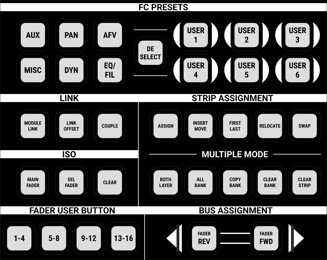
LINK | On user panel. | Operation is identical. | |
ISO | On user panel. | Operation is identical. | |
STRIP ASSIGNMENT | On user panel. | Operation is identical. | |
BUS ASSIGNMENT | On user panel. | Operation is identical. | |
FADER USER BUTTON | On user panel. | There are no electronic labels. The user button functions can be seen on the channel fader strips instead. | |
FC PRESETS | On user panel. | There are no electronic labels for the user-defined FC presets. | |
ACCESS / ASSIGN | There are no physical controls. The same options are available from the touch-screen. | ||
Lawo User Panels
The centre section can be fitted with up to two Lawo user panels. If the console is fitted with the Xtra main faders option, then the lower slot must be used for the XTRA USER PANEL. In all other cases, the two slots are freely configurable.
The table below describes the options. Unless otherwise specified, the console ships with two blanking panels.
| Part No | User Panel | Description | |
|---|---|---|---|
978/23 | XTRA USER PANEL |
| Master controls (for consoles with Xtra main faders). |
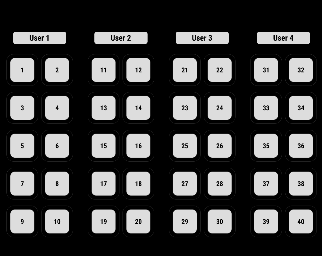
978/24 | 40 KEY USER PANEL |
| 40 user-programmable buttons. Two panels can be fitted to provide 80 buttons. |
978/25 | REVEAL FADER |
| 5 dedicated faders for revealing surround slaves. |
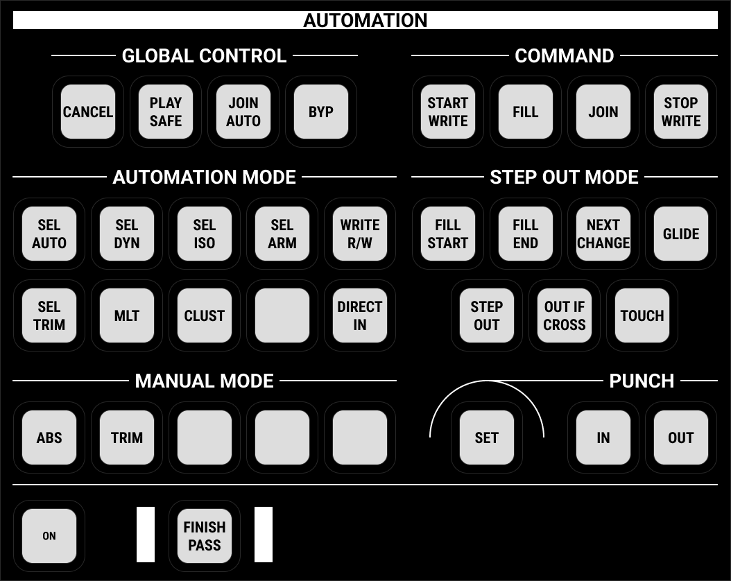
978/26 | AUTOMATION |
| Controls for the timecode automation system. |
978/28 | BLANKING PLATE | Single slot blanking panel. | |
RTW Metering
As standard, the overbridge is fitted with an RTW TM9 meter. This is a special version of the TM9, designed specifically for Lawo consoles. If the meter is removed, then a blanking panel (978/29) should be installed.
The meter provides 4 x AES3 inputs for multi-channel metering and 5 x GPI for external control. These are wired internally to the console's local I/O. The default configuration sets the AES3 inputs to follow the CRM 1 monitor source selector. Alternatively, signals can be routed directly to the meter using the console GUI.
All other functions are operated via the meter's touch-screen display. Please refer to the documentation from RTW.
The RTW meter includes a temperature-controlled fan to provide cooling at extreme temperatures (>70°C). Under normal operating conditions, the fan is inactive. When the meter boots up, the fan is tested. This means that you will hear the fan, momentarily, whenever the control surface power is applied.