vsmStudio - Combine Signal Paths
Introduction
The Combine Signals feature allows to convert existing Signal Paths into one single combined Signal Path or Tie-line. This allows to:
- Combine an Input and an Output Signal Path to represent a Loop through Device
- Combine a Target Signal Path on one layer with a Source Signal Path assigned to another layer to form a Tie-line
- Create Embedded Tie-lines out of multiple respective Signal Paths
Signal Paths based on HOME resources, that were manually modified and re-configured into Tie-lines in vsmStudio versions prior to B2484 may have to be re-created after update to B2484 or higher.
Combine into "Through-Signal"
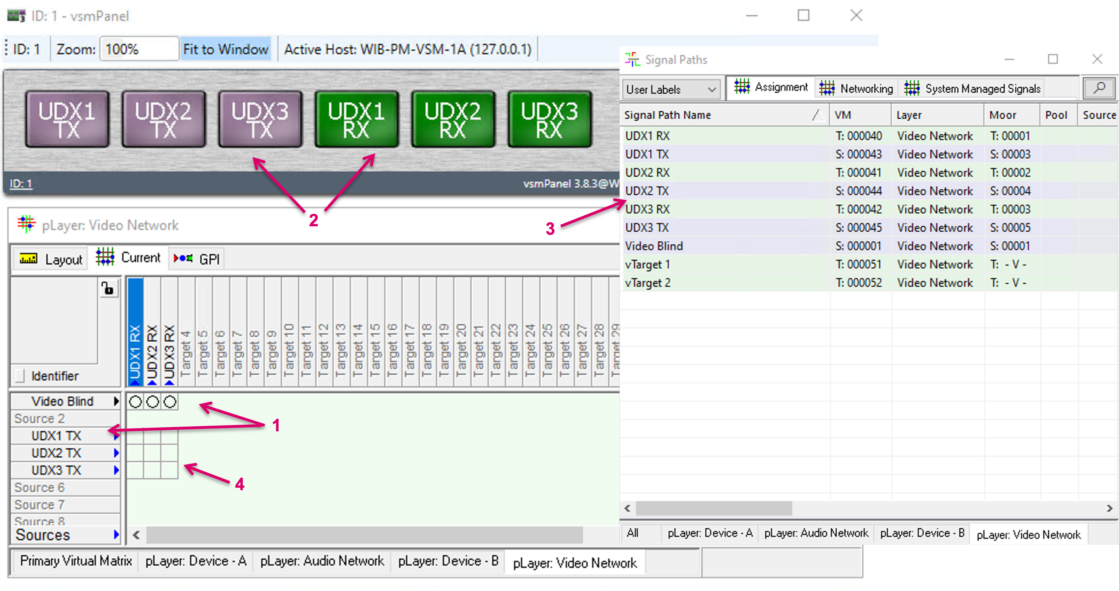
The following example shows a UDX that was initially created with separated Output and Input Signal Path (1). UDX converters, alike other processing devices like Frame synchronizers or Color correctors, are in fact “loop through”-devices, therefore these can and should be represented by one single Signal Path with both, In- and Output side. While this could be done manually, when the Signal Paths are created initially, the Combine feature allows to convert the already existing, separate Signal Paths accordingly.
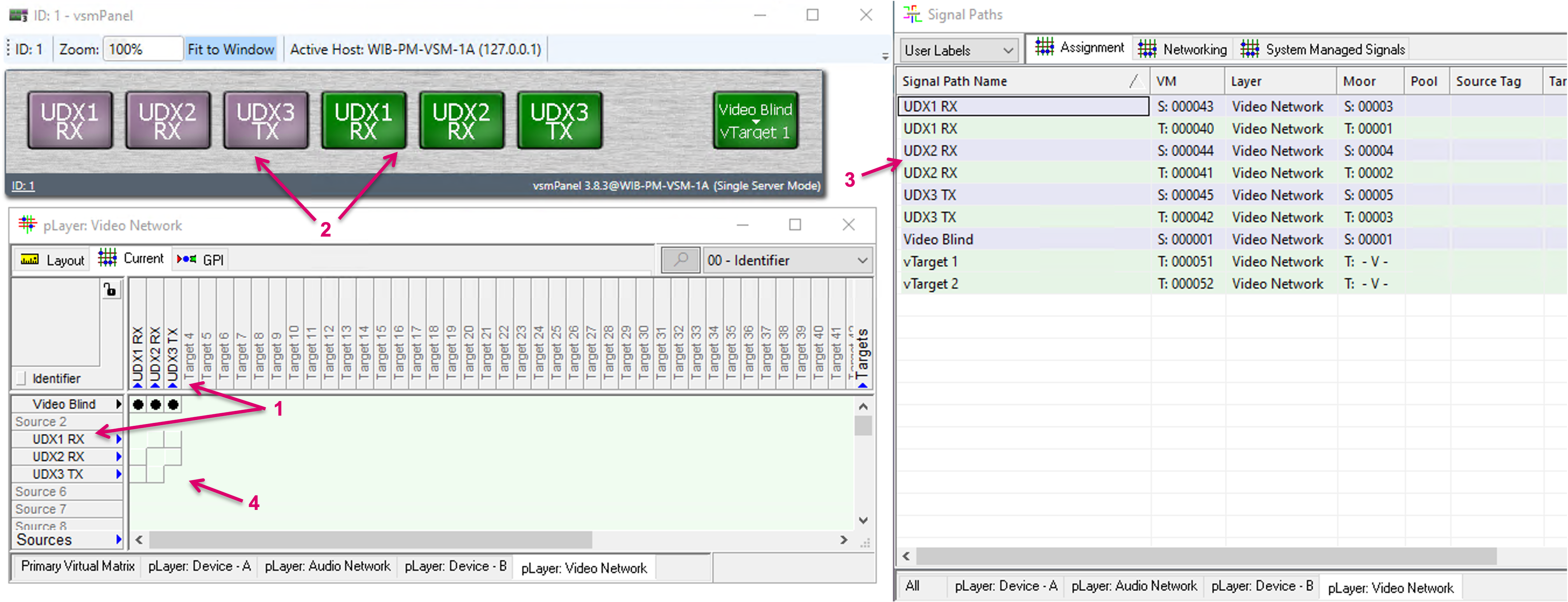
As long as Signal Paths are separate, they technically can be used already, e.g. on panel buttons (2), they show accordingly in the Matrix view and Signal Paths list with separate unique label (3). But this way, the Output of a loop-through device could also be routed to its Input (4), which effectively would not make any sense technically and most likely be an undesired option.
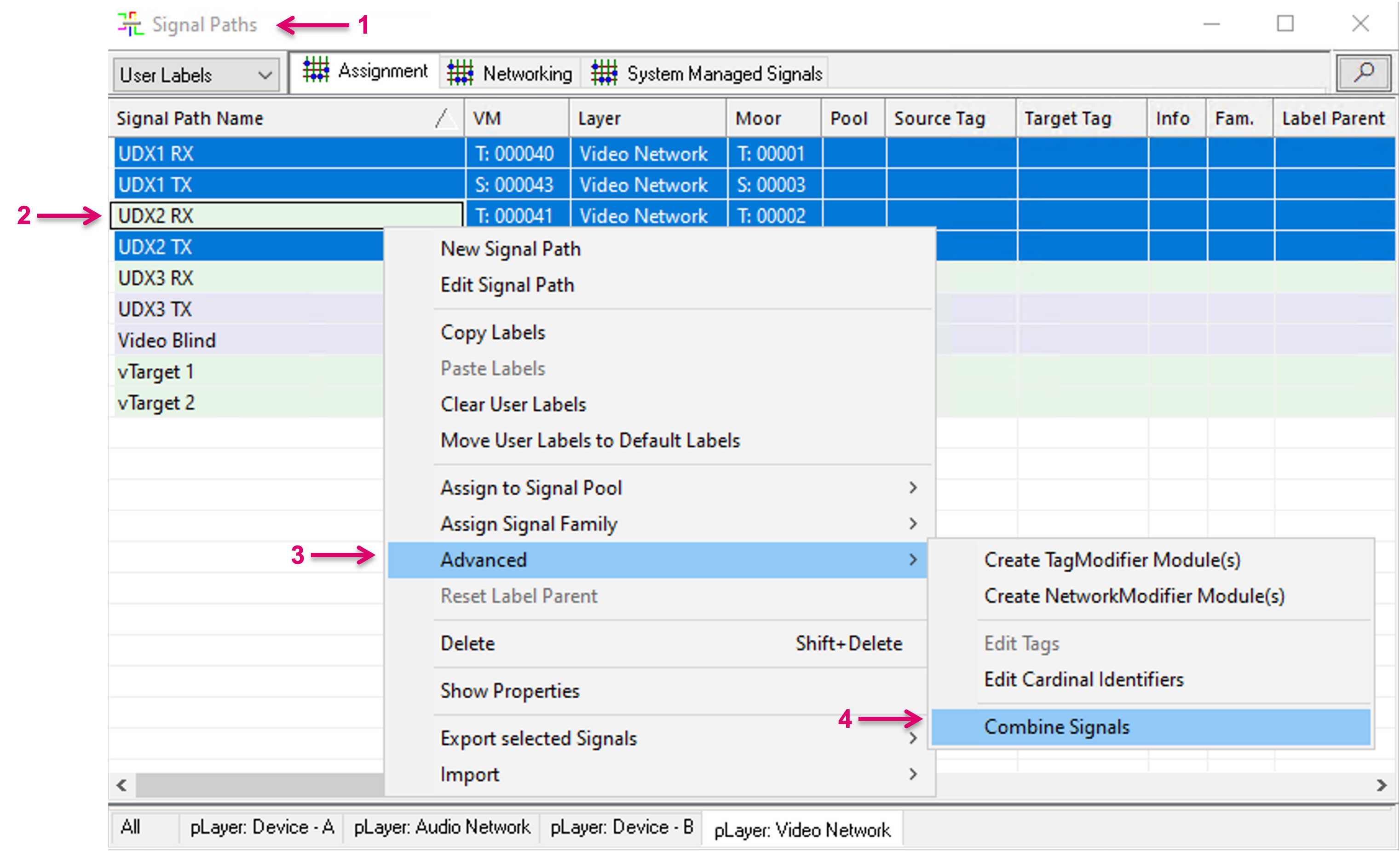
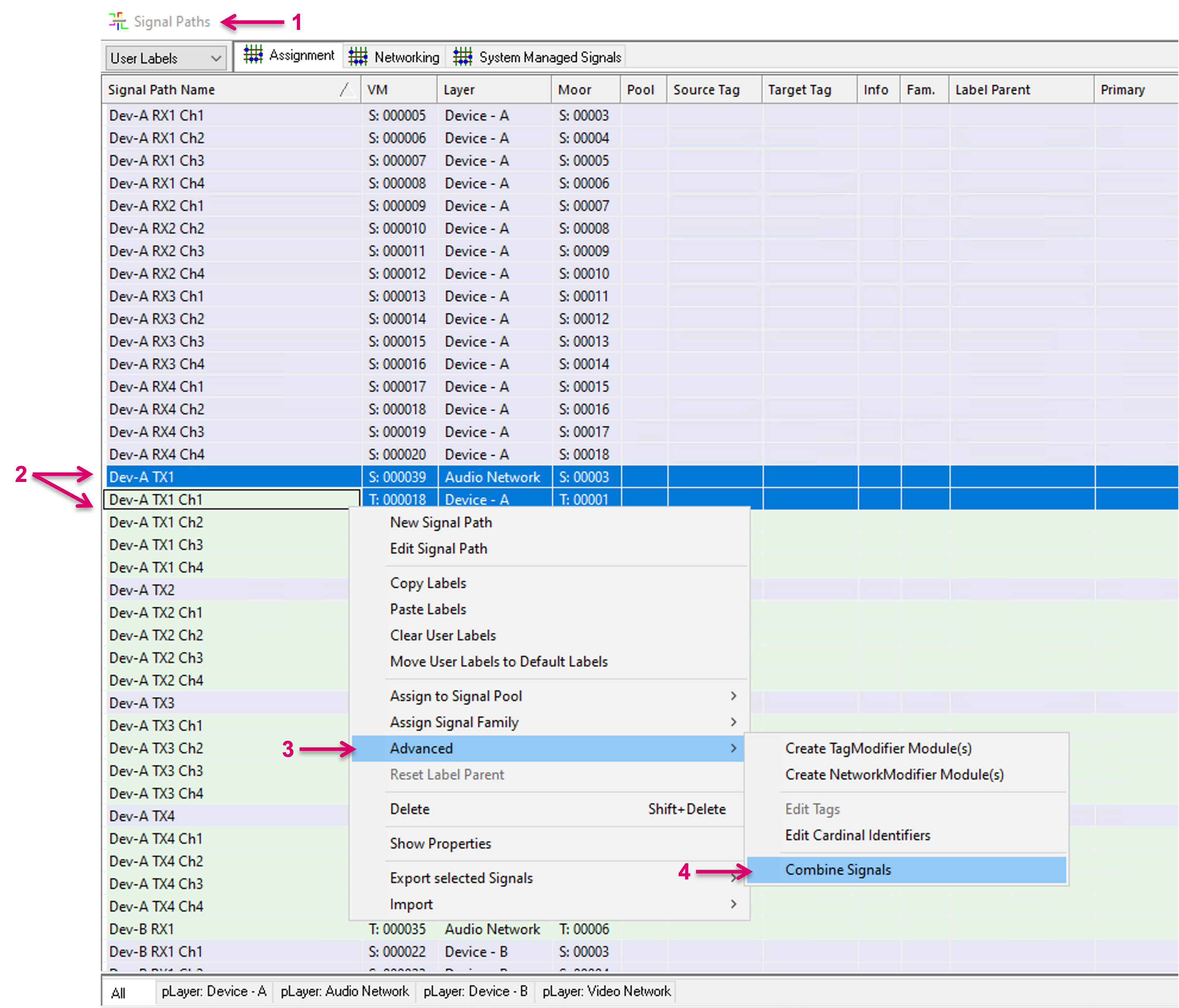
To combine separate Signal Paths, navigate to the Signal Paths list (1) and select the respective essence entries (2). Single- and multi selection is possible. With right mouse-click you can access the additional options pop-up window. In there, select, Advanced (3) and in the next pop-up window select Combine Signals (4).
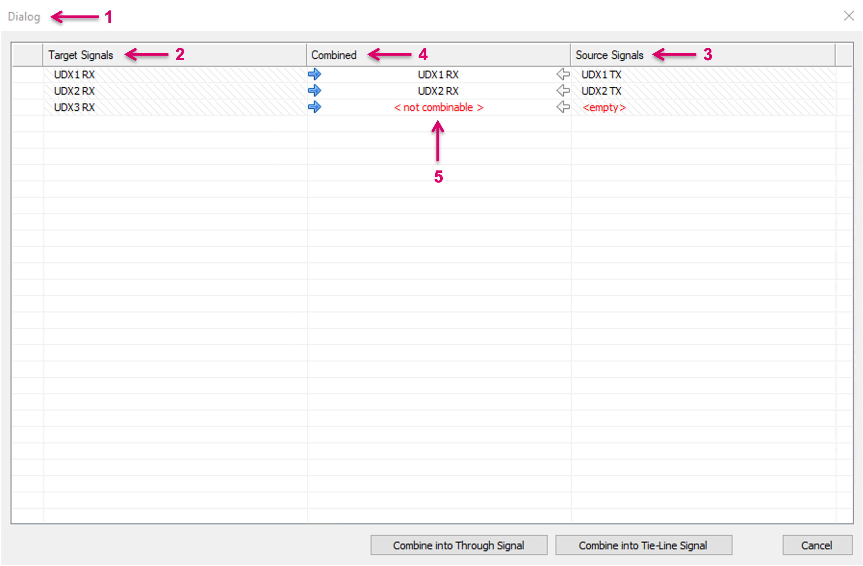
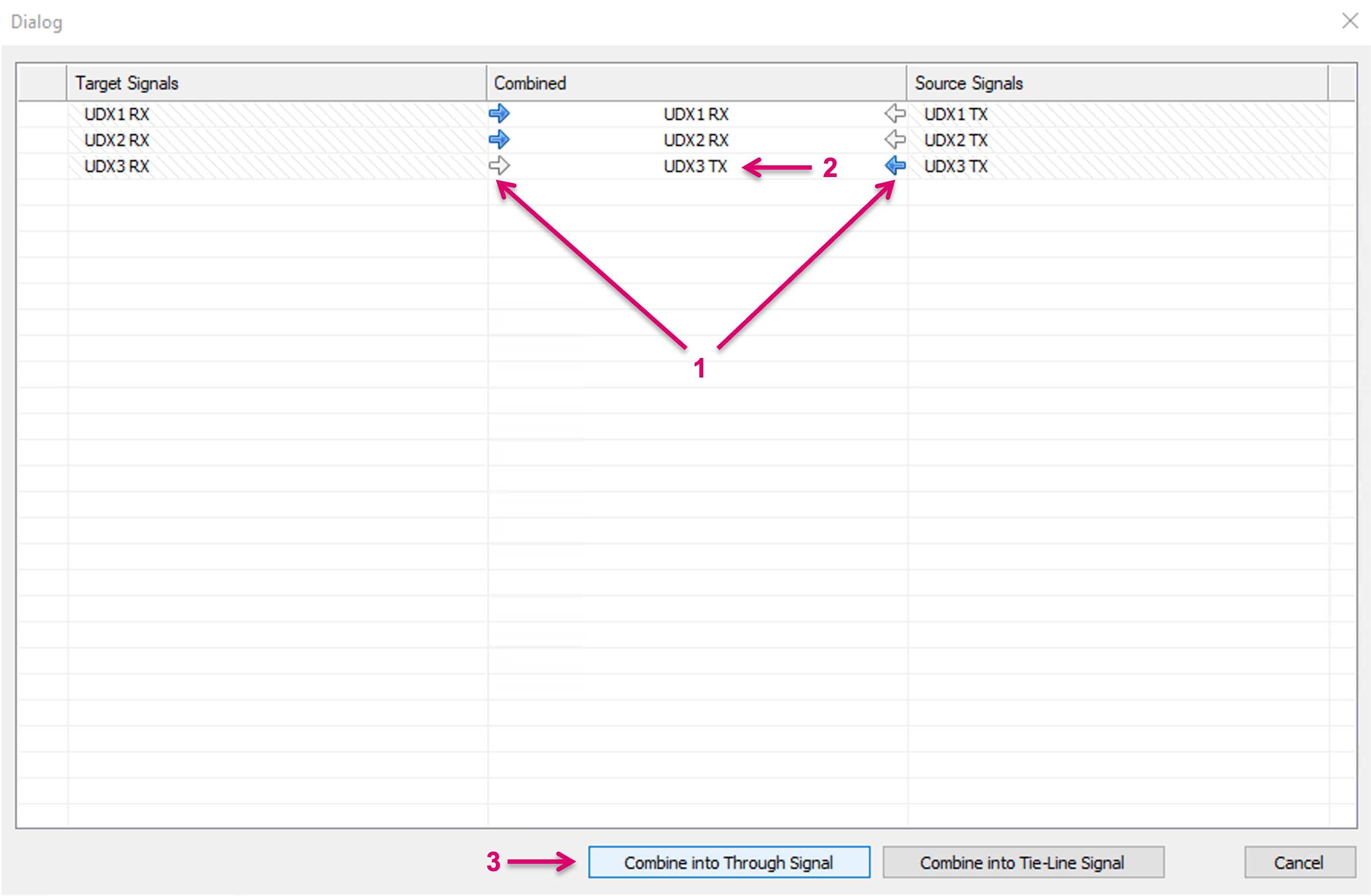
An additional Dialog window (1) will open. The Target Signals (2) and Source Signals (3) columns are filled according to the previous Signal Path selection. While the system can make assumptions of the related Signal Paths pairs based on selection and naming, a possible wrong or missing assignment can be corrected by deleting the respective entry and/ or dragging and dropping the correct Signal Path in the respective cell. The Combined column (5) indicates the resulting Signal Path instance that will be retained. It is also indicated if a pairing is not complete or cannot be combined.
By click on the little arrows left or right in the Combined column (1), it is possible to select which Signal Path instance will be retained (2). This also includes label information, applicable property settings and may affect e.g. button assignments. Please note that the “other” Signal Path of the respective pairing will be deleted and cannot be restored. Therefore, saving the configuration before making use of the combine process is recommended. Proceed with the process by clicking “Combine into Through Signal” (3).
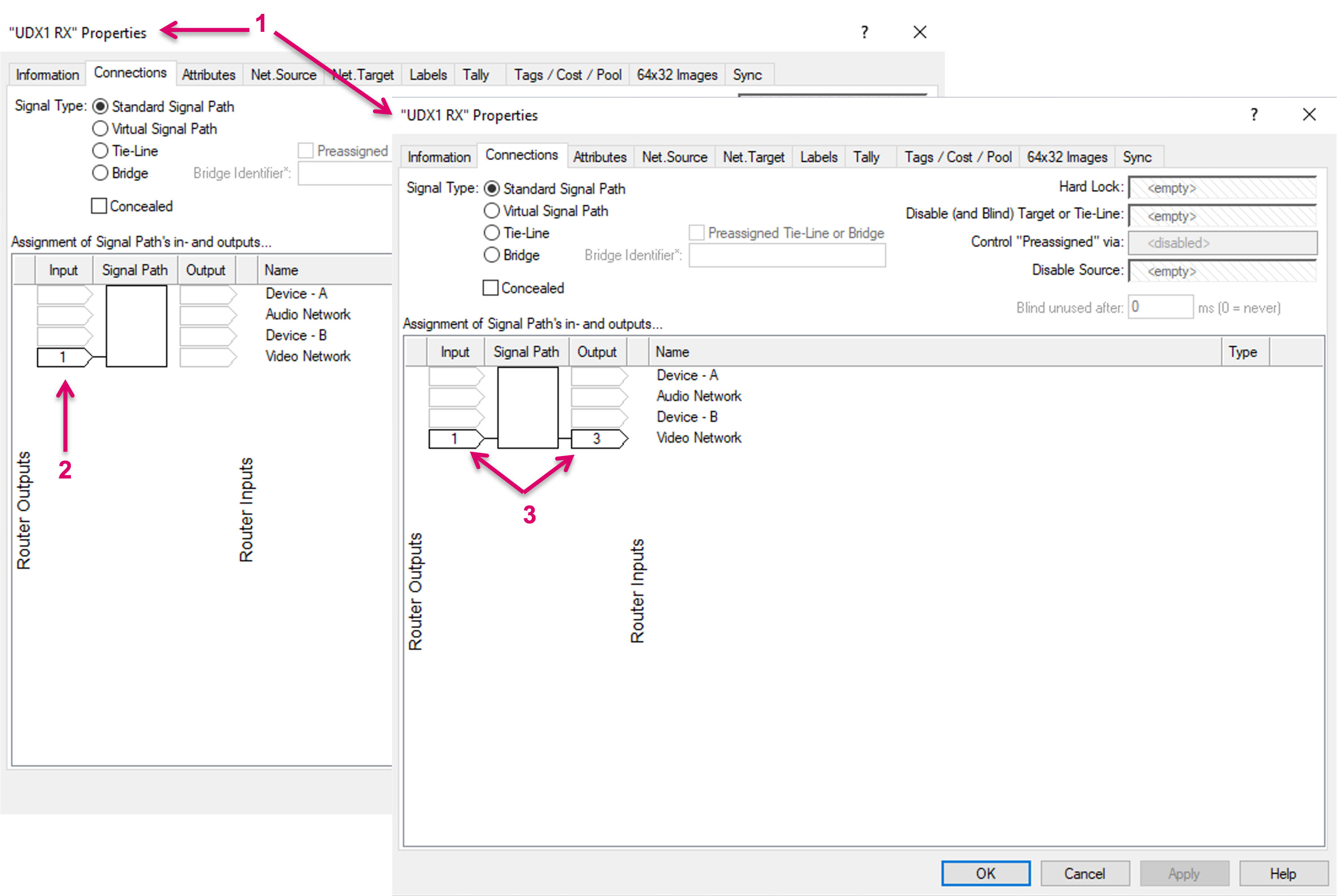
The Properties windows below (1) show the In- and Output assignments of the same, retained Signal Path before (2) and after (3) the Combine process.
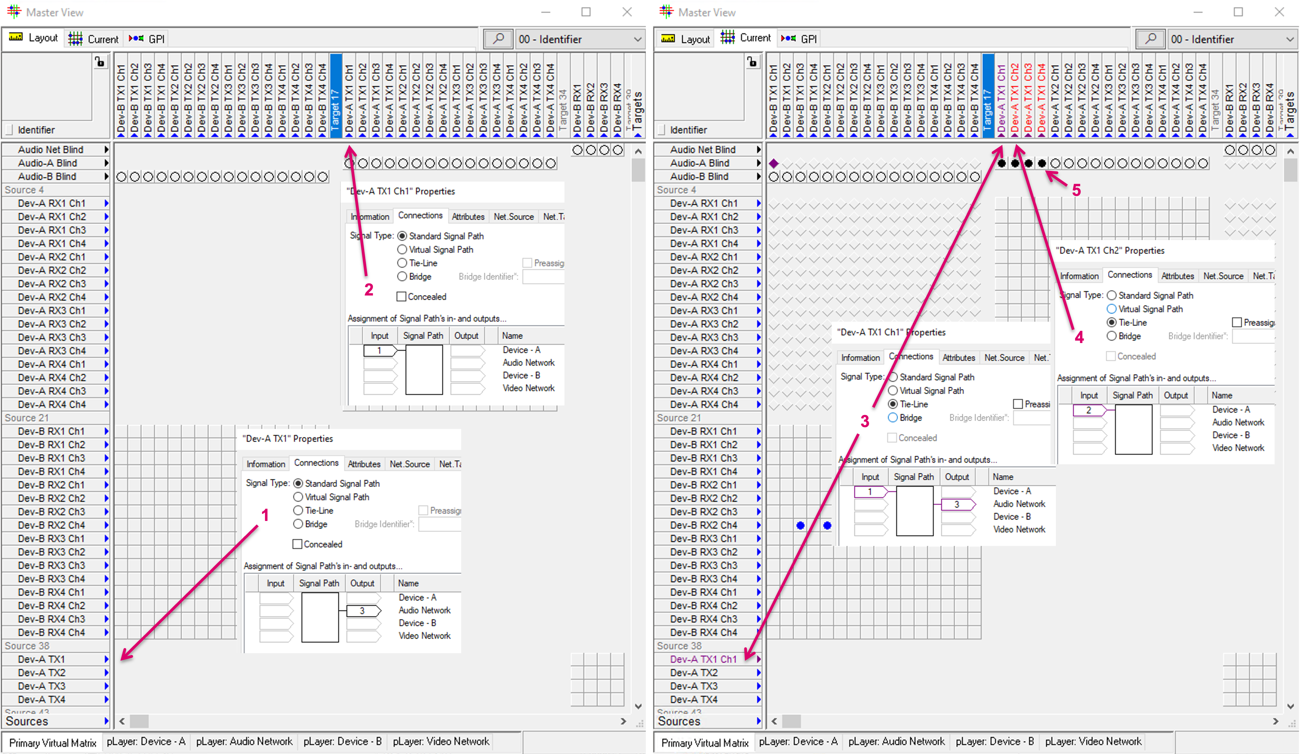
After the Combine process, only the retained Signal Path essence shows with its now In- and Output side in Matrix view (1), on Panel buttons (2) and Signal Paths list (3), while the previously existing second, separate Signal Path instance was deleted and replaced by the system accordingly. Since one and the same Signal path cannot be routed to itself, the respective crosspoint options in the matrix view are also disabled (4). As part of the process, the target side of the combined Signal Path is automatically blinded by default to avoid eventually undesired, orphan routes.
Combine into Tie-line
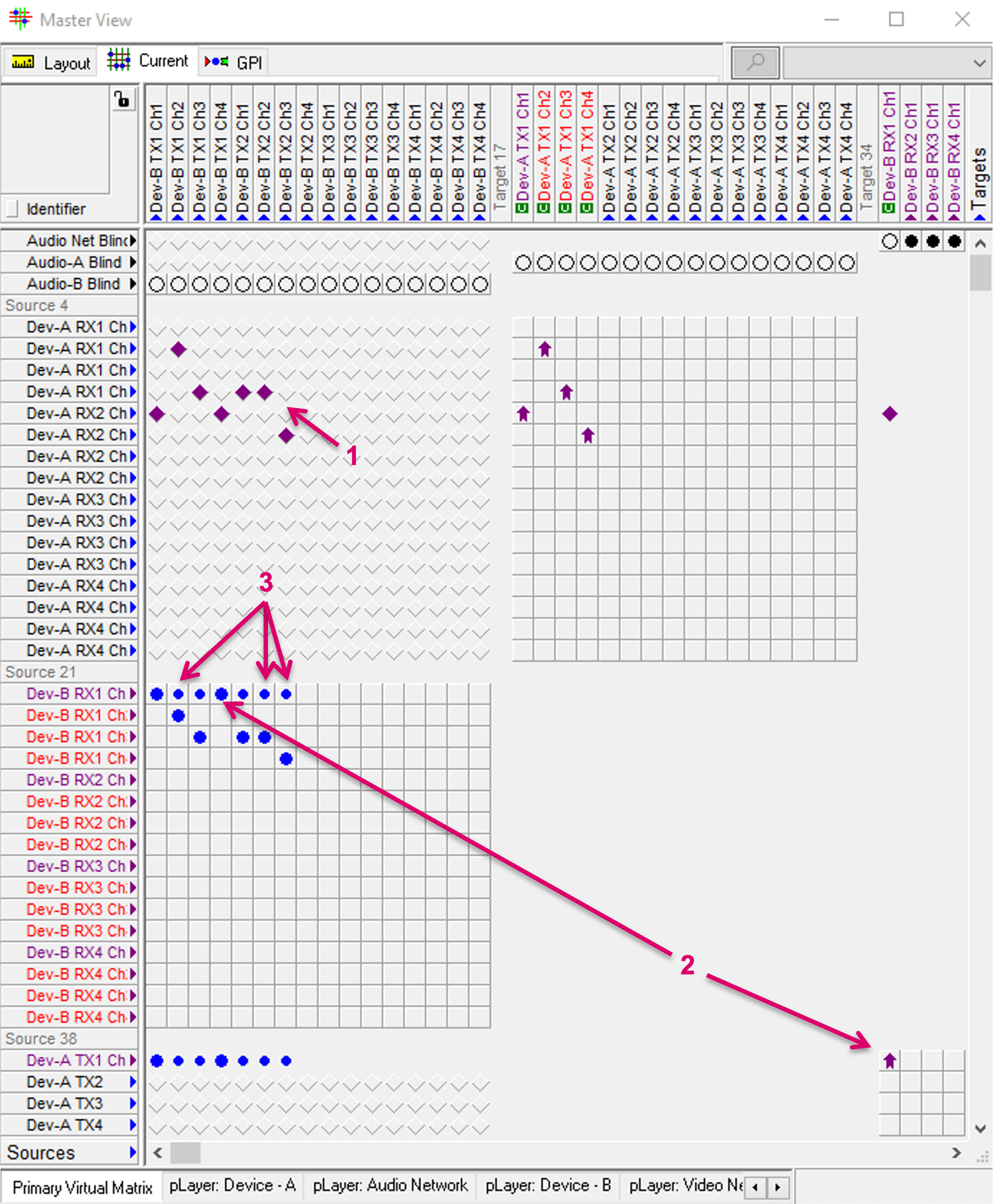
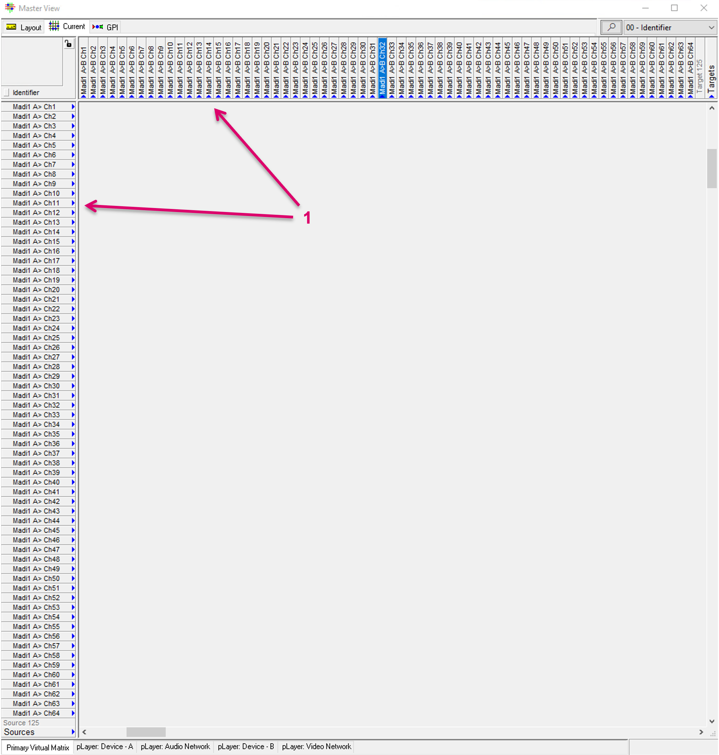
The following example shows two separate Audio routing layers with their own Source and Target Signal Paths in form of Madi Channel representations (1). A specific application may foresee that there are Madi connections between Device-A and Device-B, and the respective Channels shall be represented and handled as Tielines in vsmStudio.
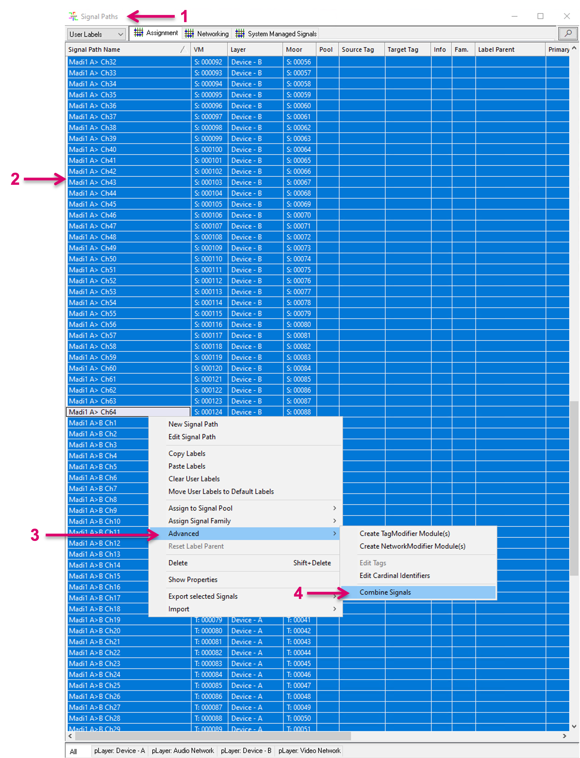
To combine the respective, separate, Signal Paths of both layers, navigate to the Signal Paths list (1) and select the respective essence entries (2). This can be all at the same time (2). With right mouse-click you can access the additional options pop-up window. In there, select, Advanced (3) and in the next pop-up window select Combine Signals (4).
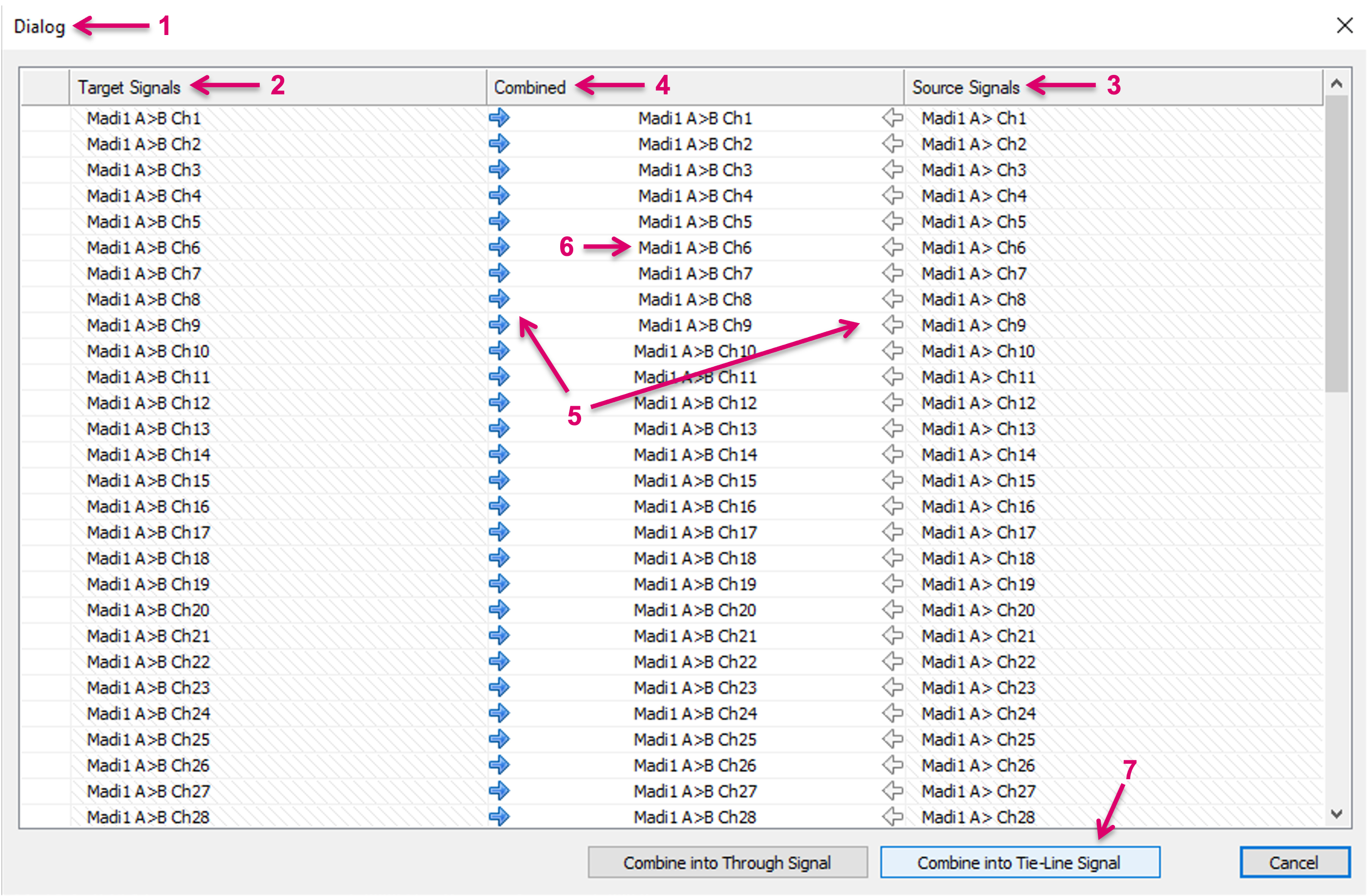
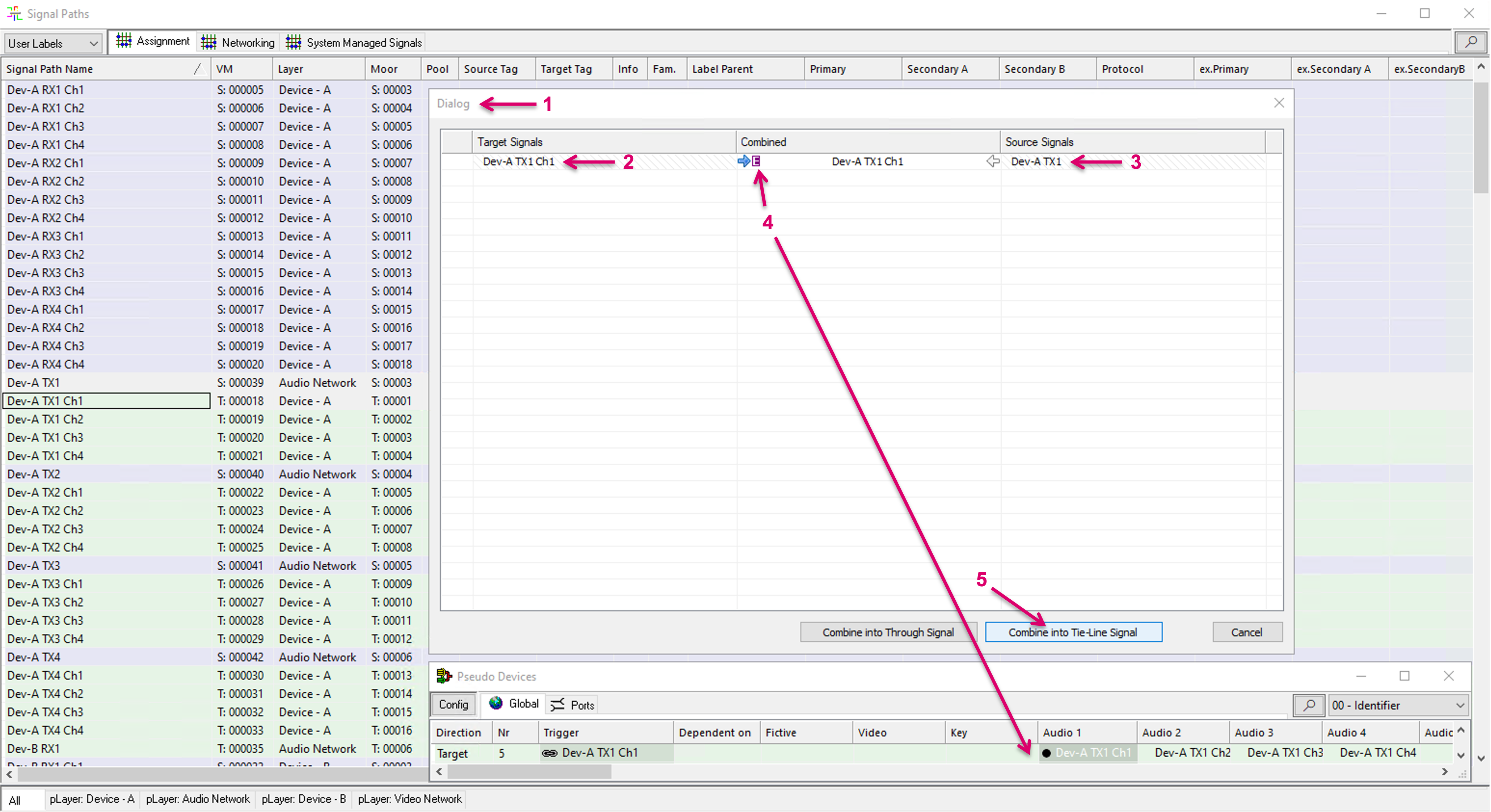
An additional Dialog window (1) will open. The Target Signals (2) and Source Signals (3) columns are filled according to the previous Signal Path selection. While the system can make assumptions of the related Signal Paths pairs based on selection and naming, a possible wrong or missing assignment can be corrected by deleting the respective entry and/ or dragging and dropping the correct Signal Path in the respective cell. By click on the little arrows left or right in the Combined column (5), it is possible to select which Signal Path instance will be retained. This also includes label information, applicable property settings and may affect e.g. button assignments. The Combined column (6) indicates the resulting Signal Path instance that will be retained. Please note that the “other” Signal Path of the respective pairing will be deleted and cannot be restored. Therefore, saving the configuration before making use of the combine process is recommended. Proceed with the process by clicking “Combine into Tie-Line Signal” (7).
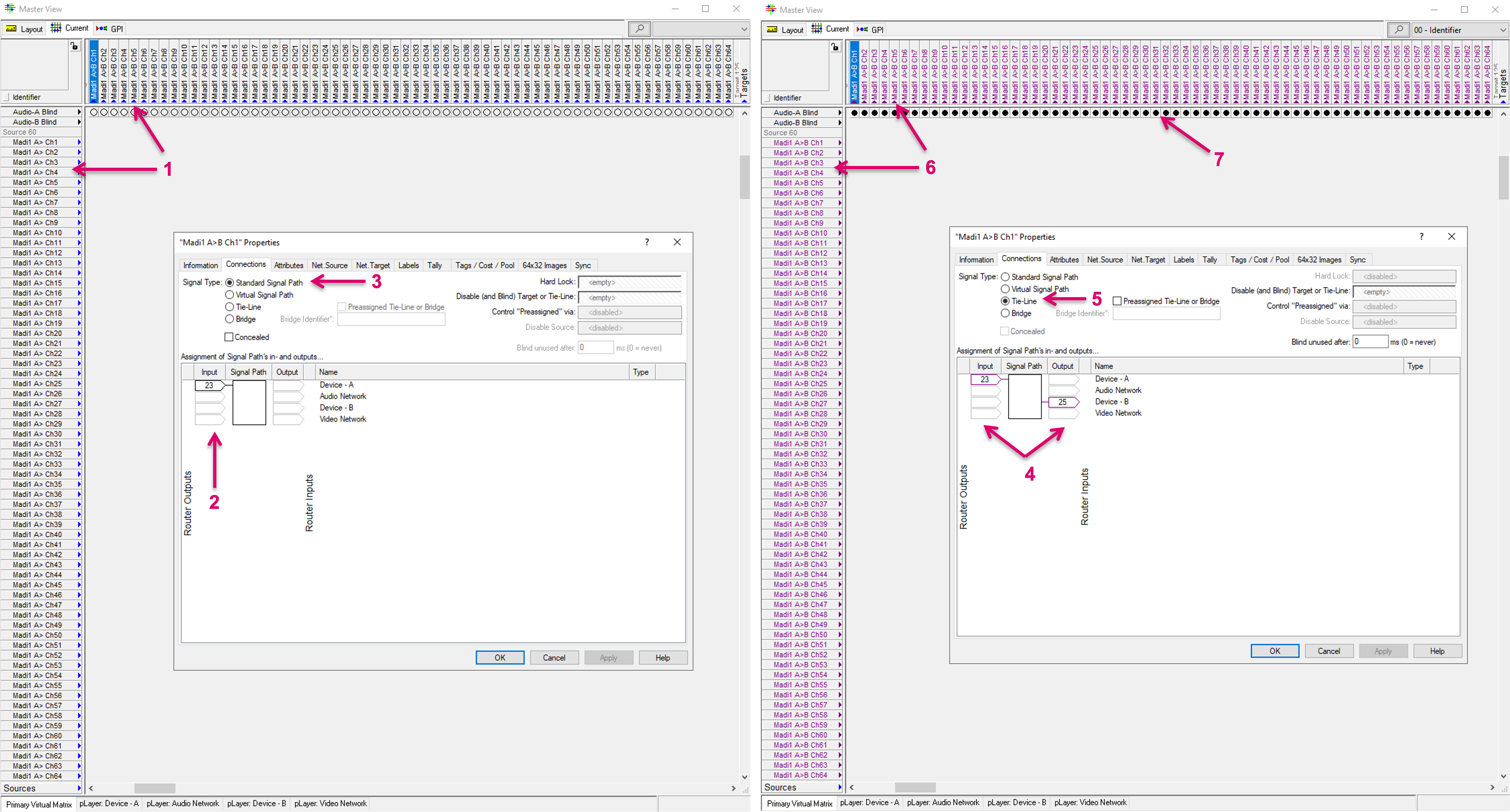
The Matrix view and Properties windows below show the appearance of In- and Output assignments of the Signal Paths before and after the Combine process.
Before, there were separate, Source and Target Signal Paths (1) where the assignment was on the In- or Output side only (2) and of type “Standard” (3). After the Combine process, only the retained Signal Path essence shows with its now In- and Output assignment (4) and changed signal type to “Tie-Line” (5) in the matrix view (6) and Signal Paths list. The previously existing second, separate Signal Path instance was deleted and replaced by the system accordingly. As part of the process, the target side is automatically blinded by default (7), to assure that the Tie-lines can be considered free and ready to be used by the system.
Combine into Embedded Tie-line
The embedded Tie-line feature in vsmStudio allows to logically link Audio Network Streams with their embedded Mono Audio Channel essences, so they can be used in a managed Tie-line workflow. This granularity down to Audio channels allows operations to route on Audio Channel level, while the system is aware and can manage the respective network routes.
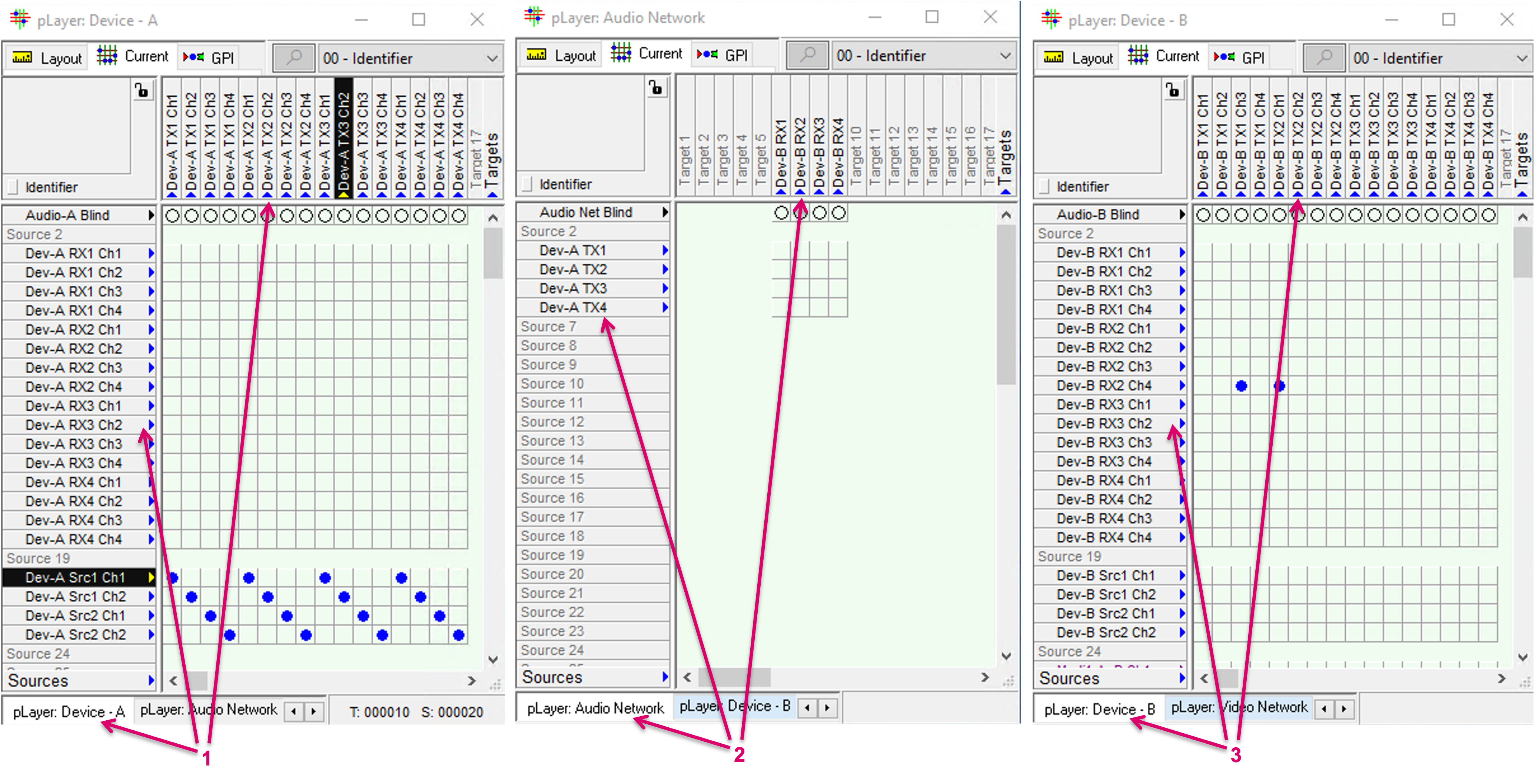
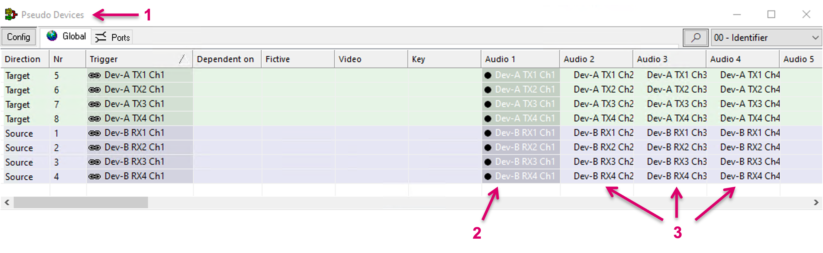
Precondition to make use of this feature is that vsmStudio has access to both, devices Network essences as well as the respective internal embedder/de-embedder routing layer. The following example shows two controlled devices, Device-A (1) and Device-B (3) and their internal routing layers, and a common Network layer with the respective Stream Senders and Receivers (2).
If all essences were already created as separate Signal Path instances in the vsmStudio configuration, the Combine feature can assist to easily create embedded Tie-lines. First step is to link all Mono Audio channels of one Network Sender or Receiver by a Pseudo Device rule. To do so, navigate to the Pseudo Devices window (1) and drag and drop the first Audio channel as trigger into the Audio 1 column (2). Assign all other related channels in column Audio 2, 3, etc. accordingly (3).
Once the Pseudo Device rule is set up, navigate to the Signal Paths window (1) and select a Network Sender or Receiver Signal Path plus the first related Audio Channel Signal Path (2). With right mouse-click you can access the additional options pop-up window. In there, select, Advanced (3) and in the next pop-up window select Combine Signals (4).
An additional Dialog window (1) will open. The Target Signals (2) and Source Signals (3) columns are filled according to the previous Signal Path selection. The system can and does make assumptions of the related Signal Paths pairs based on the selection and naming. Furthermore, the system understands if there is an existing Pseudo Device rule in place for one of the selected Signal Paths, and based on that, can assume that the respective Combine process is intended to create an embedded Tie-line. To indicate this, an additional “purple E” icon (4) is displayed. If the desire is to create an Embedded Tie-line, the suggested Combine direction, indicated by the highlighted little arrows left or right in the Combined column, should not be changed, or the result will not be as expected. The Combined column indicates the resulting Signal Path instance that will be retained. Please note that the “other” Signal Path of the respective pairing will be deleted and cannot be restored. Therefore, saving the configuration before making use of the combine process is recommended. Proceed with the process by clicking “Combine into Tie-Line Signal” (5).
The Matrix view and Properties windows below show the appearance of Stream and Mono Channel assignments of the Signal Paths before and after the Combine process.
Before, there was a Source Signal Path on the Network layer (effectively an Embedder Output) (1) and separate Target Signal Paths on the device’s Audio layer (effectively the Embedder Channel Inputs) (2). Signal Paths type was “Standard”. After the Combine process, only the retained Signal Path essence shows for the Network resource and now combined first Mono Audio Channel (3). Signal Path type is now set to “Tie-line”. In addition, the Audio Channels, as previously defined in the Pseudo Device rule, were also converted into Tie-lines but in a one-leg only assignment (4). As part of the process, the Signal Path targets are automatically blinded by default (5), to assure that the Tie-lines can be considered free and ready to be used by the system.
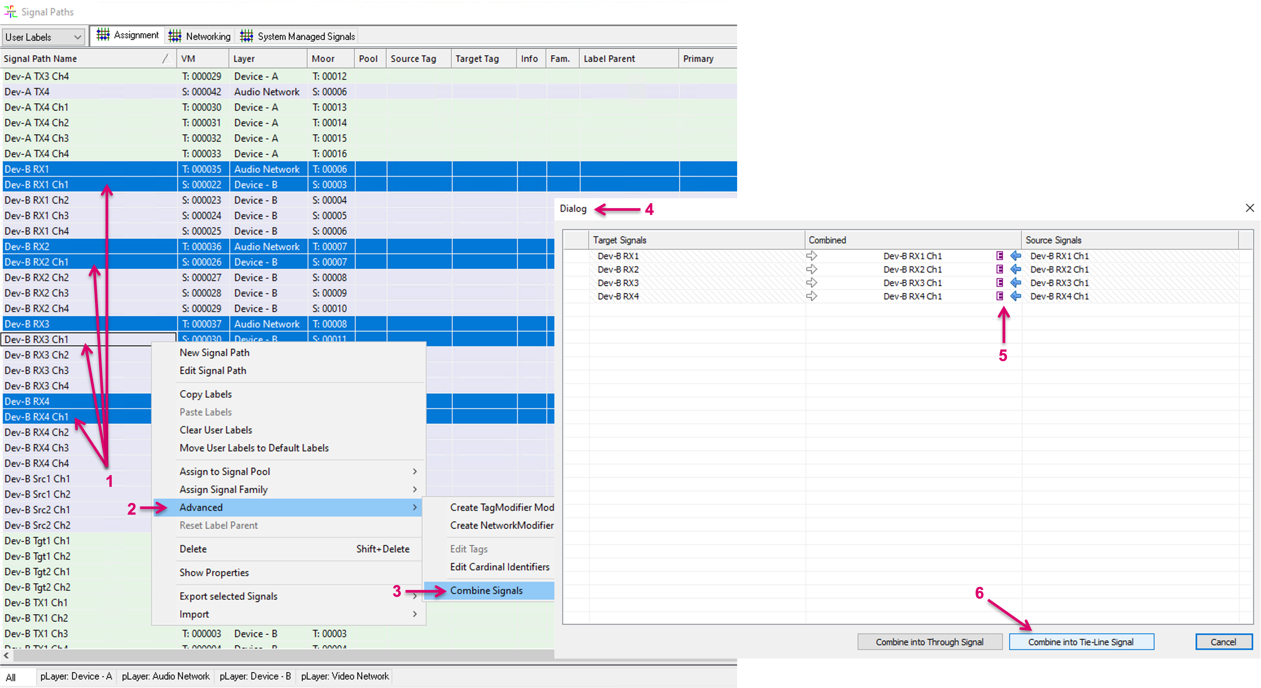
Multi-selection is also possible for the Combine into Embedded Tie-line process. Once the Pseudo Device rule is set up, navigate to the Signal Paths window and select the desired Network Sender or Receiver Signal Path plus the respective first Mono Audio Channel Signal Paths (1). With right mouse-click you can access the additional options pop-up window. In there, select, Advanced (2) and in the next pop-up window select Combine Signals (3). In the opening Dialog window (4), the Target and Source Signals columns are filled according to the previous Signal Path selection. The system can and does make assumptions of the related Signal Paths pairs based on the selection and naming. Please check, if all pairings are correct and modify, where needed, by dragging and dropping Signals from the Signal Paths list. As described above, the system understands if there are existing Pseudo Device rules in place for any of the selected Signal Paths, and based on that, can assume that the respective Combine process is intended to create embedded Tie-lines. To indicate this, an additional “purple E” icon (5) is displayed. If the desire is to create an Embedded Tie-line, the suggested Combine direction, indicated by the highlighted little arrows left or right in the Combined column, should not be changed, or the result will not be as expected. The Combined column indicates the resulting Signal Path instance that will be retained. Please note that the “other” Signal Path of the respective pairing will be deleted and cannot be restored. Therefore, saving the configuration before making use of the combine process is recommended. Proceed with the process by clicking “Combine into Tie-Line Signal” (6).
The matrix view after the combine process shows the Tie-line routing option between the Mono Audio Channel layers (1). If a route is triggered on Mono Audio Channel level, the system will utilize a free leg on any of the so configured Audio Network Stream Senders and will trigger the respective Network route accordingly (2). If the same Mono Channel was already routed, it won’t utilize another Network Stream Sender. The respective assignments beyond the first channel of a Network Stream resource, configured as embedded Tie-line are indicated and displayed with slightly smaller blue dot icons (3).