Distributed Multi Viewer - Module


Introduction
The Distributed Multi Viewer module in vsmStudio is tailormade to embrace the unique IP cluster multi viewer architecture of the V__matrix C100 vm_DMV., and embeds it into the overall broadcast workflow.
After the basic internal configuration of the DMV cluster with the number of desired Heads, Monitoring Objects and unique Sources, the module provides a one button push read-out of the DMV configuration via a valid communication to the DMV Cluster master. On top of this, all DMV related Signal paths are automatically created in the vsmStudio configuration. During the operational workflow the Distributed Multi Viewer module automatically manages the various layers inside the DMV cluster and presents the user with a single step Source to PIP routing workflow. The module manages all configured DMV head processors in one or more dynamic head pools. This allows to dynamically attach head processors to a desired destination during runtime and share a single processor among multiple possible destinations.
The dynamic resource handling with the Distributed Multi Viewer module requires VSM to exclusively control routing inside the DMV. No 3rd party system or device internal patching and routing that may bypass VSM, may be executed. 3rd party systems, like theWall, can control PIP routing via vLayer in vsmStudio though.
DMV Cluster Setup
Configure the DMV cluster according to the device instructions and based on the current physical and computing resources.
Things to consider:
- The amount of created Source IDs for Video, Audio and Metadata must not exceed the amount of calculated processing capacity of the cluster. Source IDs reflect unique physical sources into the DMV cluster.
- The amount of created Monitoring Objects can and should be a multiple of the amount of source IDs to allow unique physical sources to be bundled in various combinations (e.g., same Video with different Audio assignments) or physical Signal being “wrapped” inside Virtual Signal paths that basically represent separate Signal Identities with e.g., own label information and tally status.
- Even same content in combination with different user requirements, e.g., PPM Channel-count or monitoring settings, requires multiple Monitoring Objects.
- The number of created Heads must not exceed the amount of calculated processing capacity of the cluster.
- Create the max. amount of Analog and/ or Digital Clock Elements per Head, in respect to what needs to be displayed as part of Monitor layouts on the system.
- Create the max. amount of Textbox Elements per Head, in respect to what needs to be displayed as part of Monitor layouts on the system.
Before the Distributed Multi Viewer module can work, you will have to delete all entries in the Source Index lists, clear all Source ID to Monitoring Object assignments, as well as Monitoring Object to PIP assignments inside the DMV. Do so, even if the default DMV setup/ scripting process included these settings. The module currently expects a “clean” DMV to manage all underlying resources.
Setup Communication Ports to the DMV
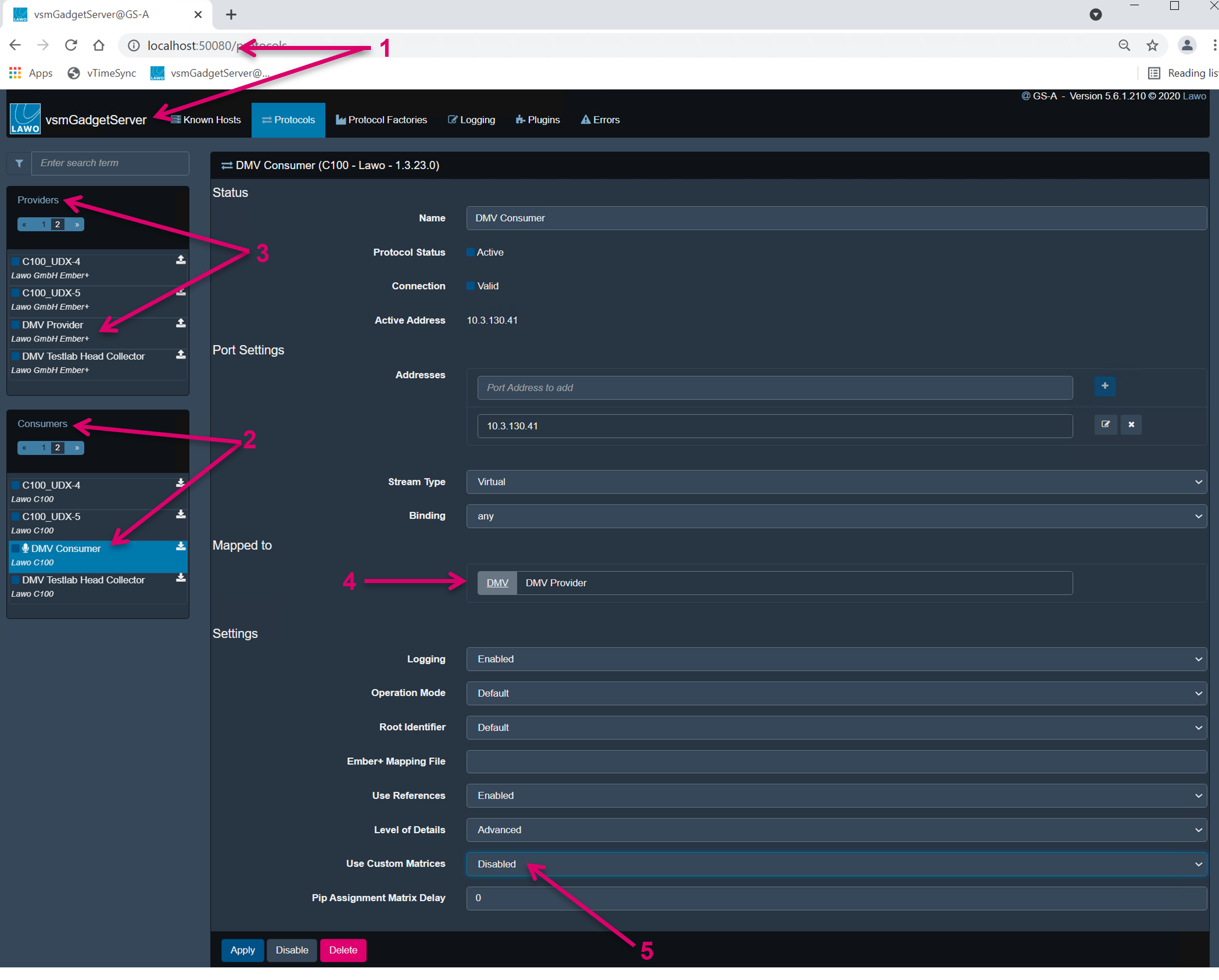
- In vsmGadgetServer (1) set up a C100 protocol consumer port (2) to the DVM Cluster master node.
- Set up an Ember+ protocol provider port (3) for the DMV towards vsmStudio and map the DMV consumer port to this connector (4).
- Since we do not need manual Crossbar matrix support, Disable the respective option (5).
- In vsmStudio setup an Ember+ Consumer port for the vsmGadgetServer connection.
Create the Distributed Multi Viewer module
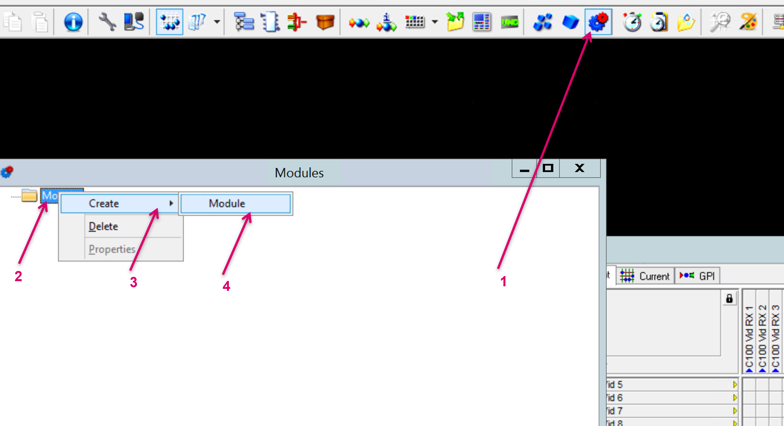
Navigate to the Modules section (2) from the vsmStudio toolbar (1), right-mouse-click on Modules, select Create (3), select Modules (4).
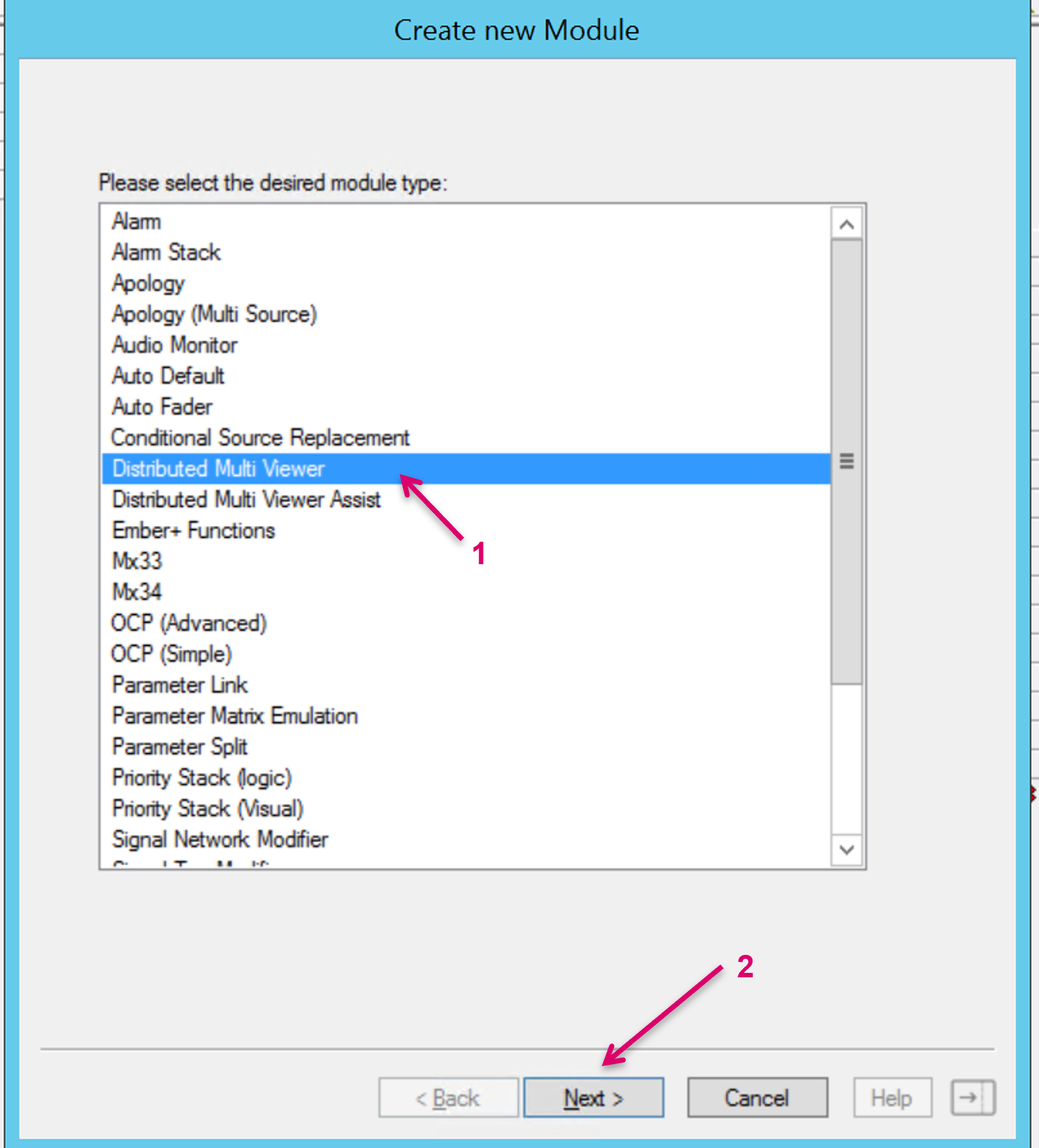
From the opening window select Distributed Multi Viewer (1) and confirm with Next (2)
It is also possible to start the setup process from the Monitor Management section (1). There, just open sub-node Devices, select Create and Device (2).

Set up and execute the Distributed Multi Viewer module
All relevant settings are done in the editor view of the “Distributed Multi Viewer” module.
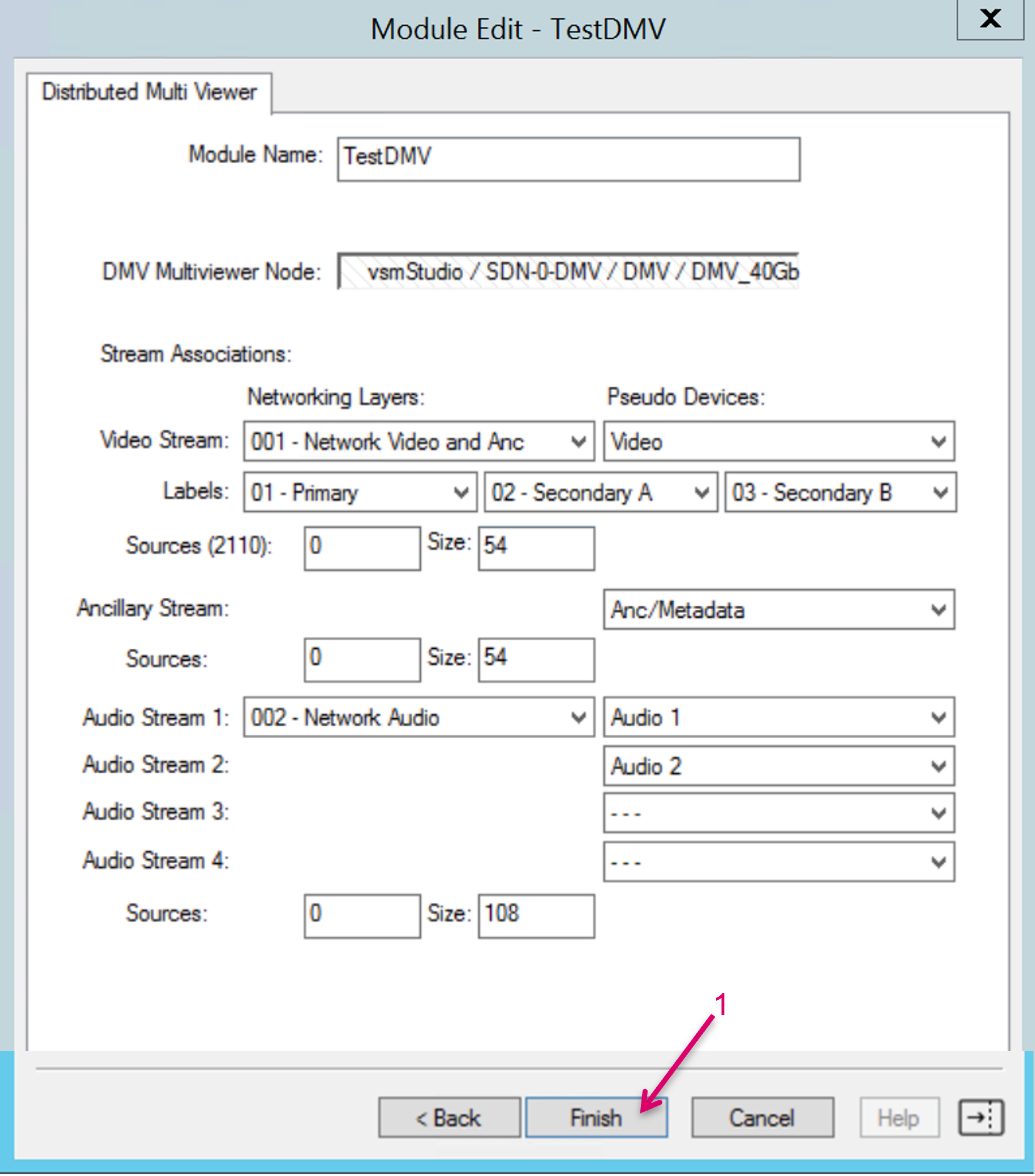
Make sure all settings as described below are done and correct BEFORE executing the configuration process by clicking "Finish"!
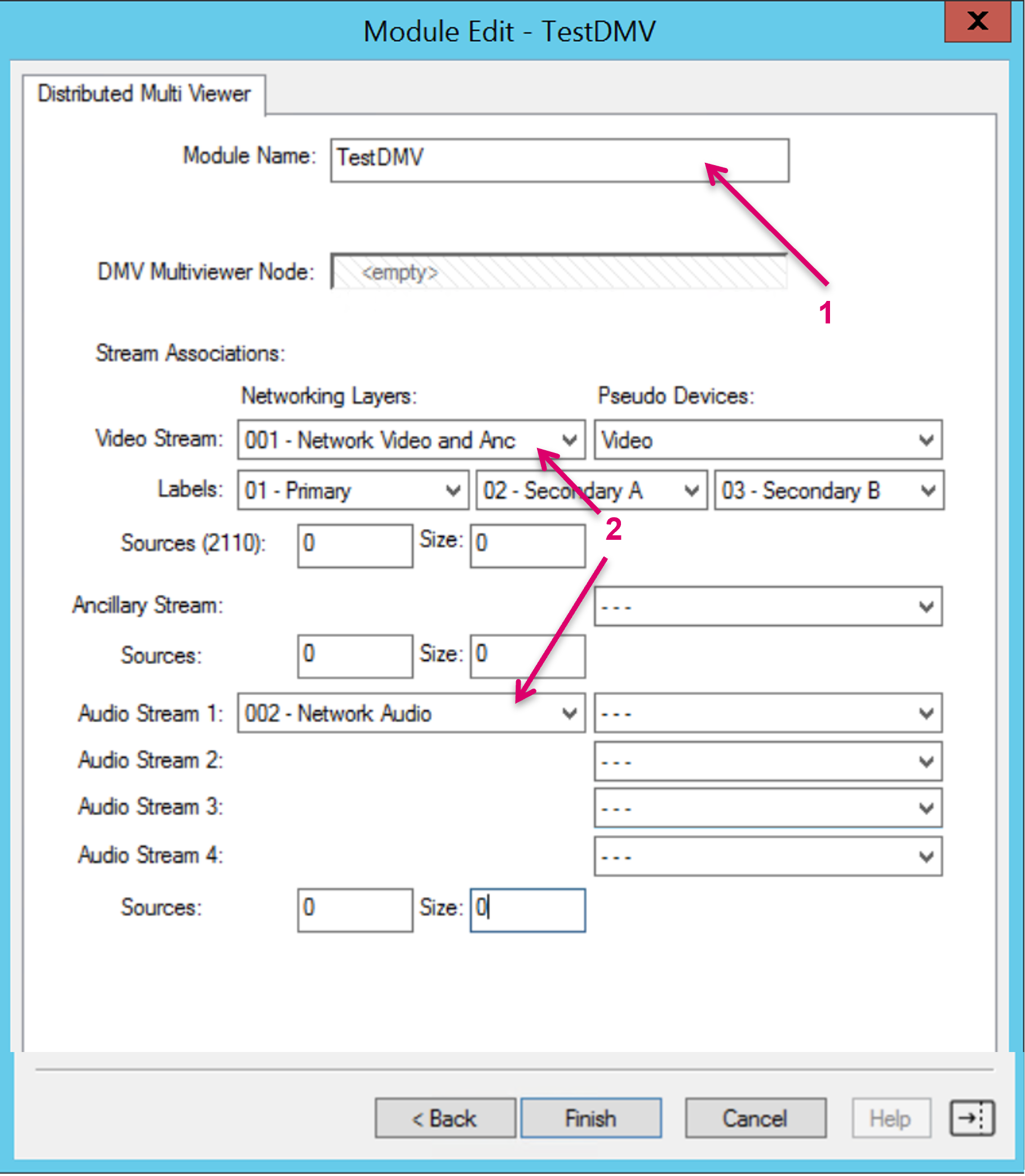
First set a Module Name (1) and select the respective Networking Layers from the drop-down menus (2).
The Network Layers have to exist, or be respectively configured beforehand and it is mandatory that Video and Anc/Metadata Signal Essences are configured on the same Network layer in vsmStudio!
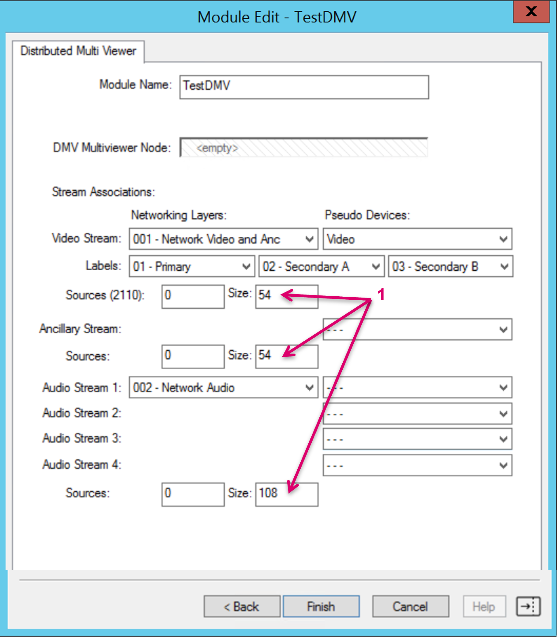
Set the start point and range for the Video, Audio and Metadata Source Index list entries in the DMV that will be addressed by the module (1).
This range needs to match the DMV configuration. Consider that the DMV will use the same ID 1:1 on each List for Video AND Audio AND Metadata for 2022 and SDI ranges. Even not all of these standards may yet supported with the Distributed Multi Viewer module, especially in case of Audio (where in 2110 multiple Stream sources/IDs per one Video ID may be used) this is important to be considered when setting the ranges in the DMV configuration. Make sure IDs will not overlap.
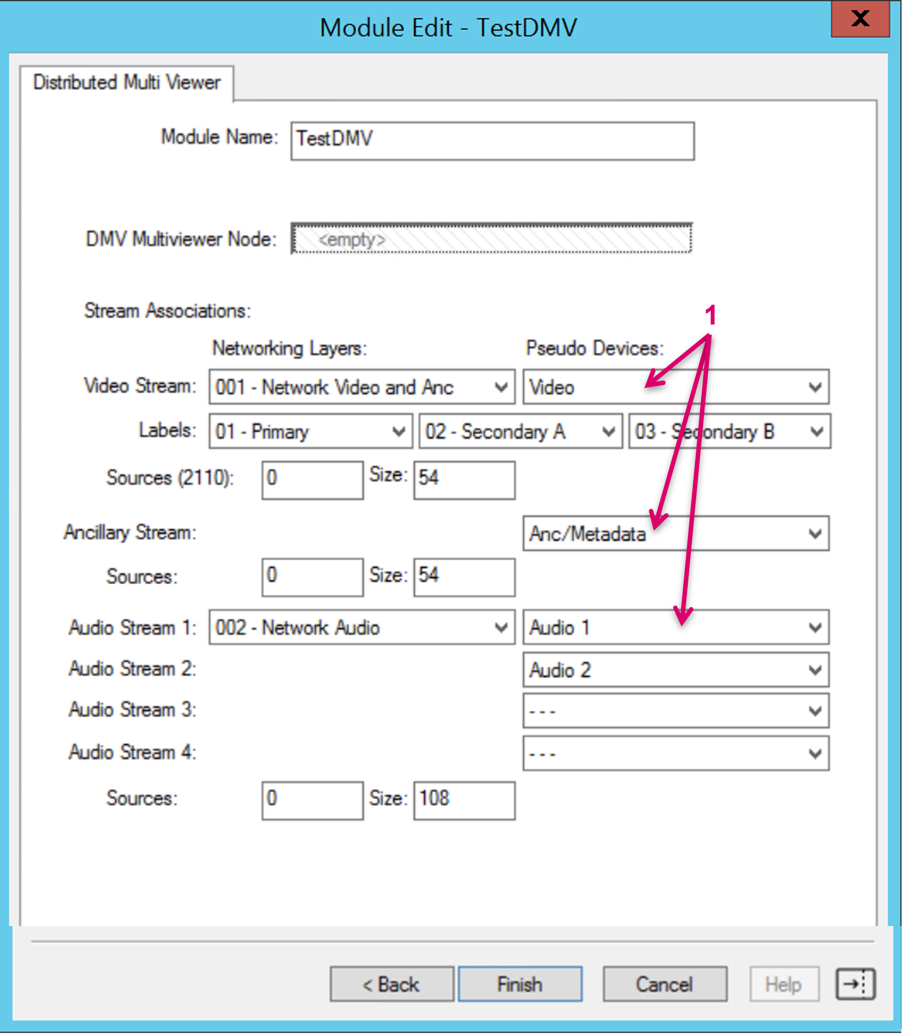
Select the respective Pseudo Device Column per category from the drop-down menus.
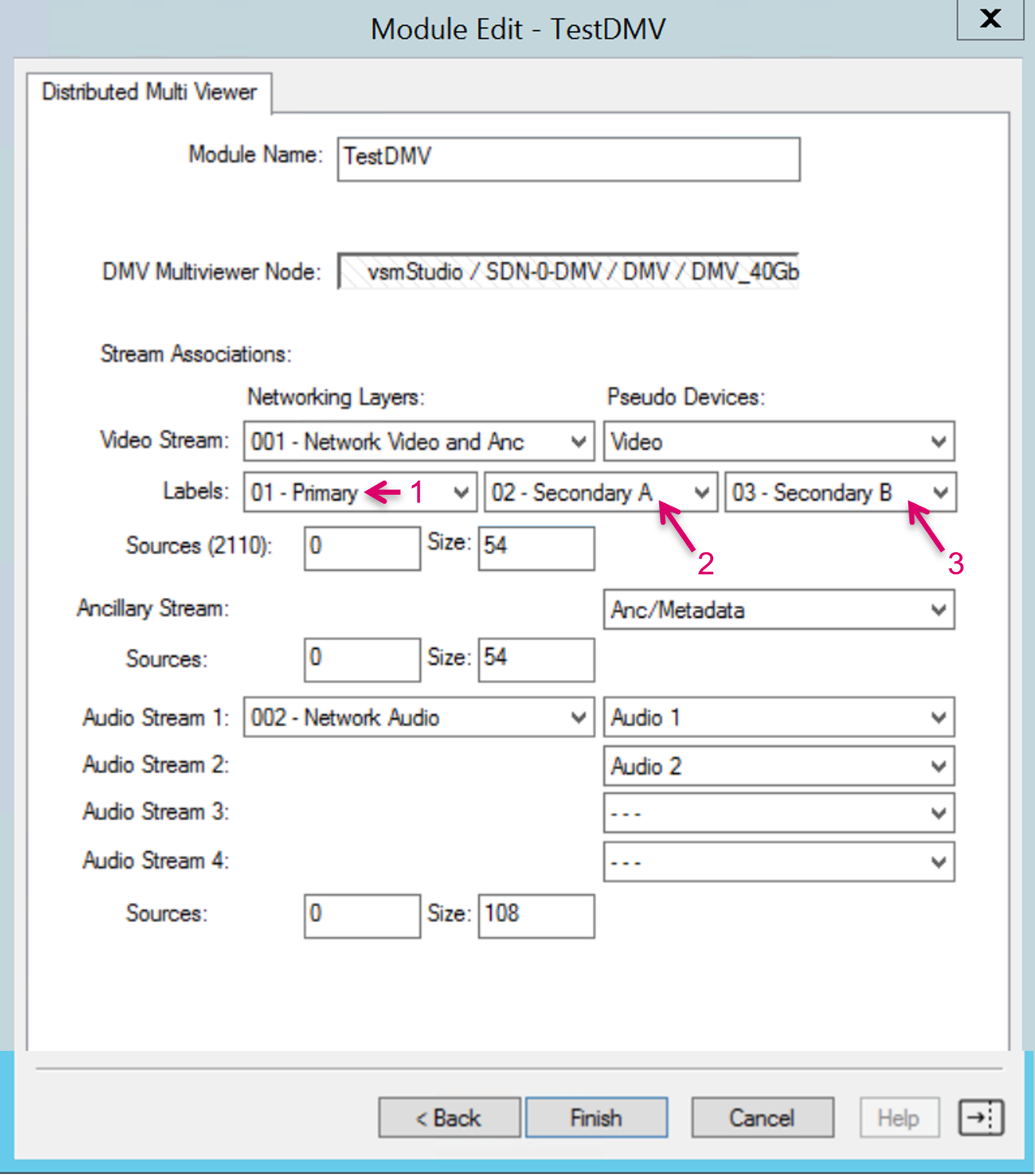
Define the vsmStudio label levels to be sent to the DMV. The underlying mapping is predefined and static as follows:
- Label selection box (1) = DMV {MONITORING_OBJECT_VIDEO_SOURCE_LABEL}
- Label selection box (2) = DMV {MONITORING_OBJECT_USER_LABEL_0}
- Label selection box (3) = DMV {MONITORING_OBJECT_USER_LABEL_1}
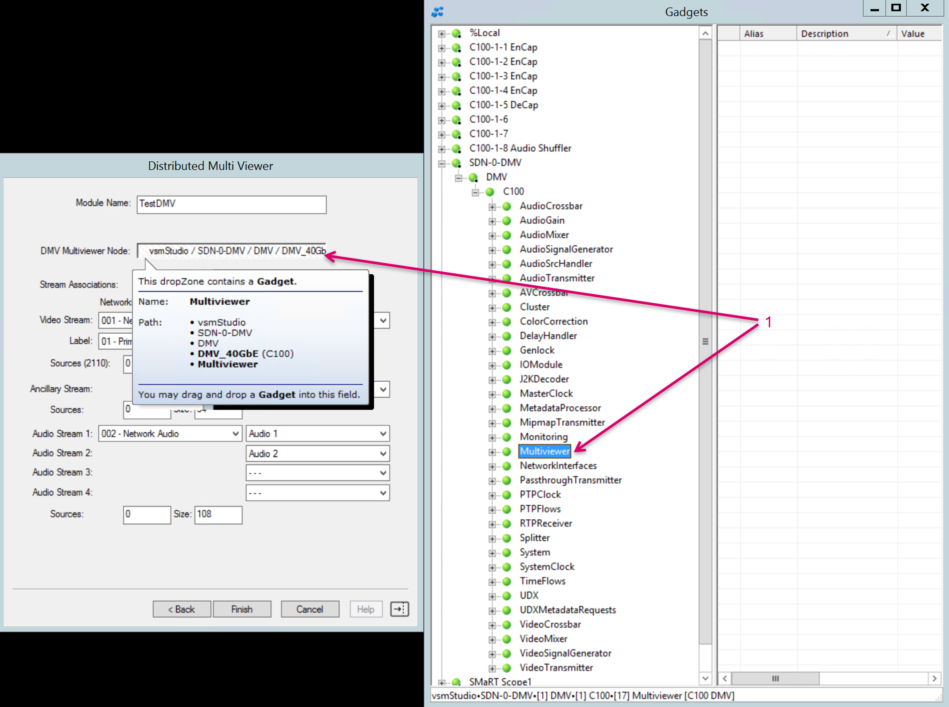
Open the Gadget tree, expand the DMV parameter tree and drag & drop the Multiviewer node into the respective drop-zone.
Verify that all settings are correct. Then execute the module and configuration process by clicking "Finish".
Module Processes
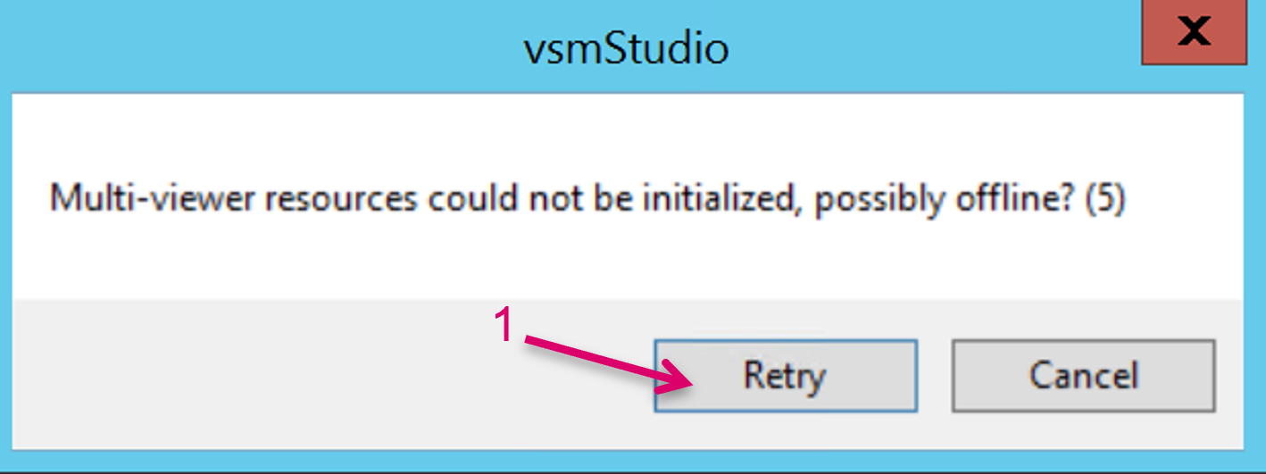
Multiple background processes are triggered every time the Finish button is clicked. Depending on the system size, this overall process may take a while to be finalized. There is no progress status indicator, but while the editor window stays open, the process is still underway. A successful execution can be assumed if the editor window is automatically closing. Under some circumstances the execution may fail, and an Error message will pop up. In such case leave the Error message open and check the protocol communication to the DMV, possibly including also a disable/enable toggle on the protocol consumer port in vsmGadgetServer (vsmGadgetServer to DMV). Afterwards click Retry.
The background processes triggered by the module include:
- The readout of all relevant information about the DMV configuration, like number of heads, Monitoring Objects, SDI inputs, etc. via the Multiviewer node that was assigned in the module.
- The automatic creation of Signal paths within the System Managed Signals tab (1), as well as on the general Assignment tab (2) of the Signal Paths view, according to the read-out DMV resource information.
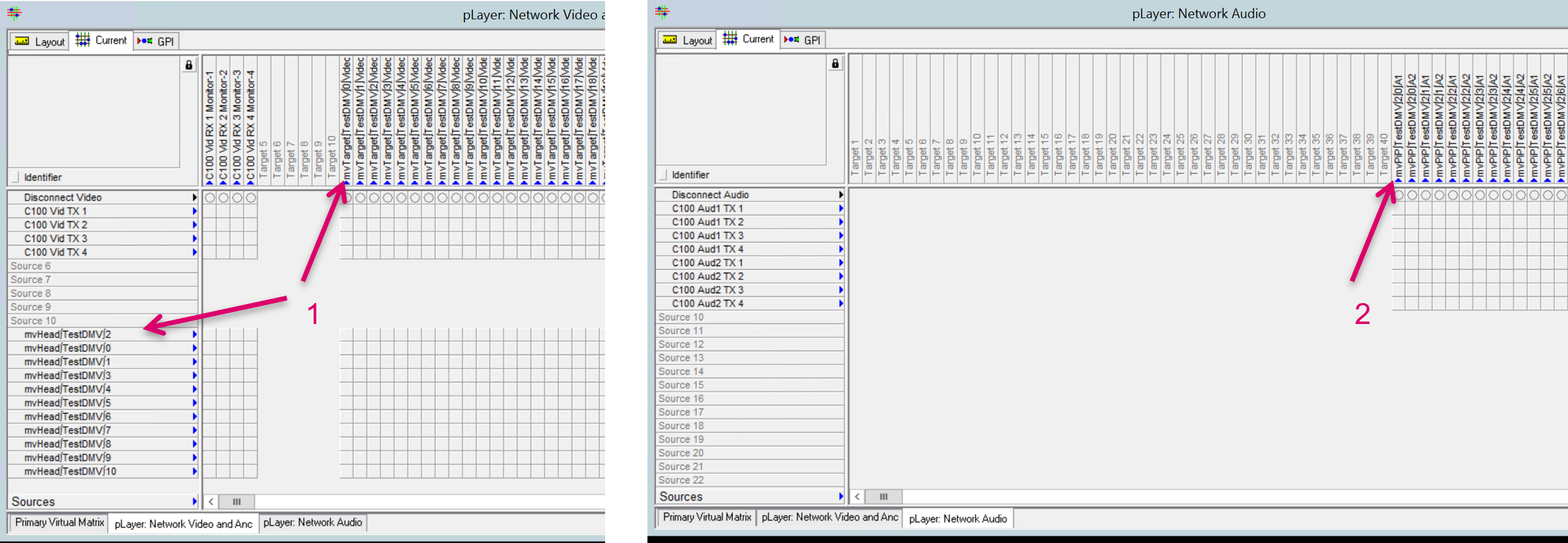
- The automatic creation of an additional Matrix layer (3) containing SDI Input sources (4) and PIP targets (5), according to the read-out DMV resource information. Only SDI Sources of the DMV are currently supported!

vsmStudio will automatically extend the size of the respective Network Layers and add the System Managed Signals in this new range. [In the Picture example below, the size before the module execution was 10/10 on VideoAnc (1) and 40/40 on Audio layer (2).]
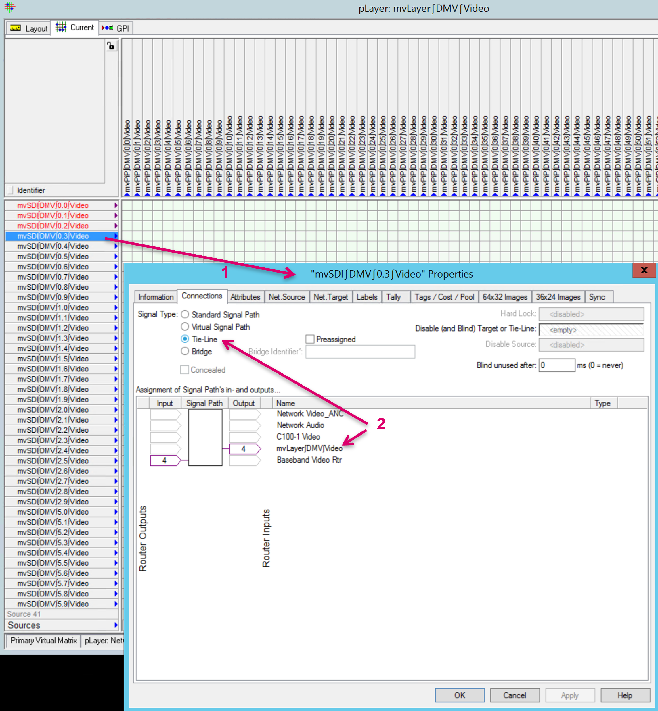
If required, it is possible to modify the created SDI Input sources (1) afterwards and change the Signal Type from Standard Signal Path into Tielines if these Inputs are fed for instance from a Baseband router (2).
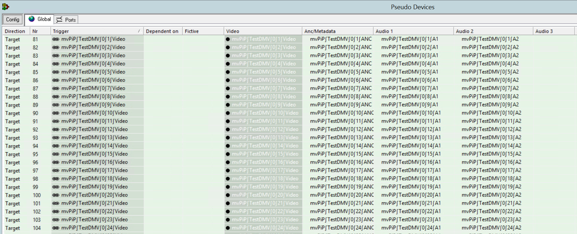
- The module will also automatically create Pseudo devices based on the Pseudo Devices assignments in the module.
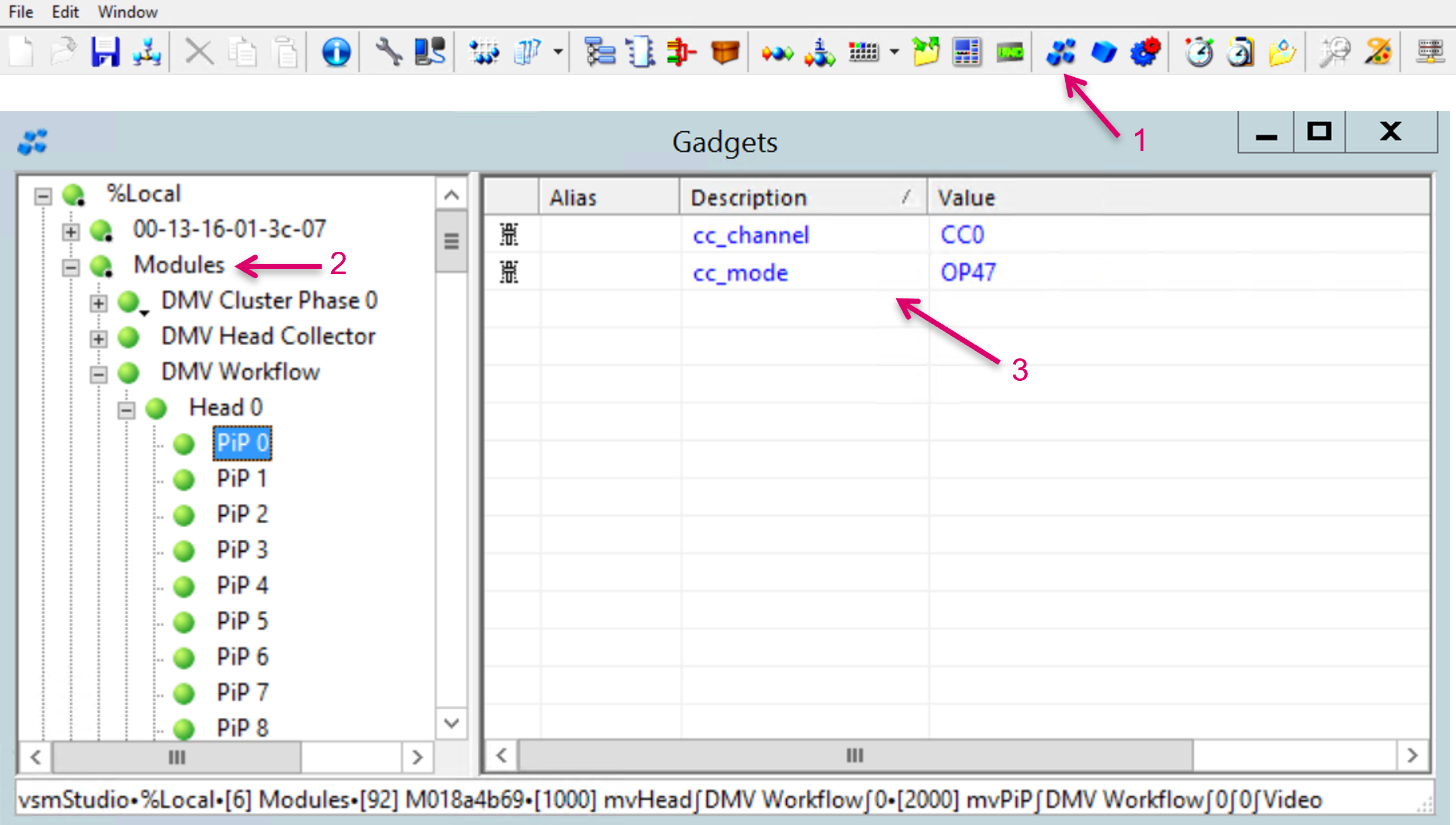
- The module will extract various workflow related Parameters and expose them in Gadgets (1). Under sub-node Modules (2) are currently two Closed Caption related workflow parameters listed (3).
- In order to access these parameters dynamically from a panel via DAS, the system already creates MetaGadget (1) entries for all PIPs (2) automatically, with the respective Gadget parameters already assigned (3).

It is possible to re-run the module after initial creation, at a later time, e.g., if the DMV Cluster is extended and therefore resources added in the DMV configuration. That said, scaling down is not supported, means none of the already existing System Managed Signals will be deleted even if the DMV configuration was changed in this direction.
The bottom controls to run the module look slightly different if opening the editor view of an already existing Distributed Multi Viewer module (1).
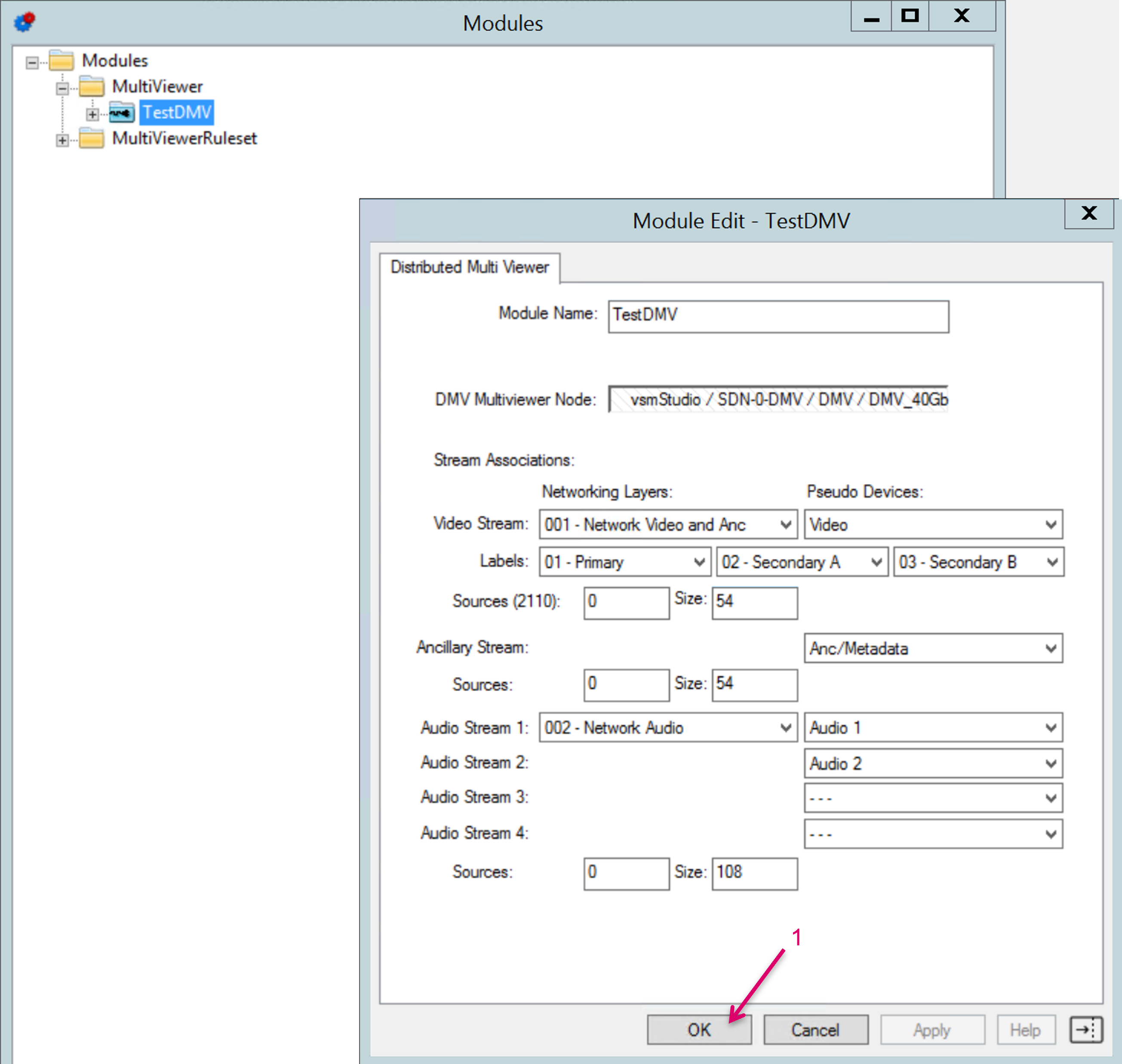
After running the module it is strongly recommended to save, close and re-open the vsmStudio configuration before proceeding with the following configuration steps.
Create and assign HeadPools
With the Distributed Multi Viewer module, vsmStudio manages DMV Monitoring Objects as well as Head resources in Pools. While the handling of Monitoring objects is done as a background process without manual intervention, the HeadPools must be created to allow, even in a pooled resource process, for dedicated usage of specific physical resources.
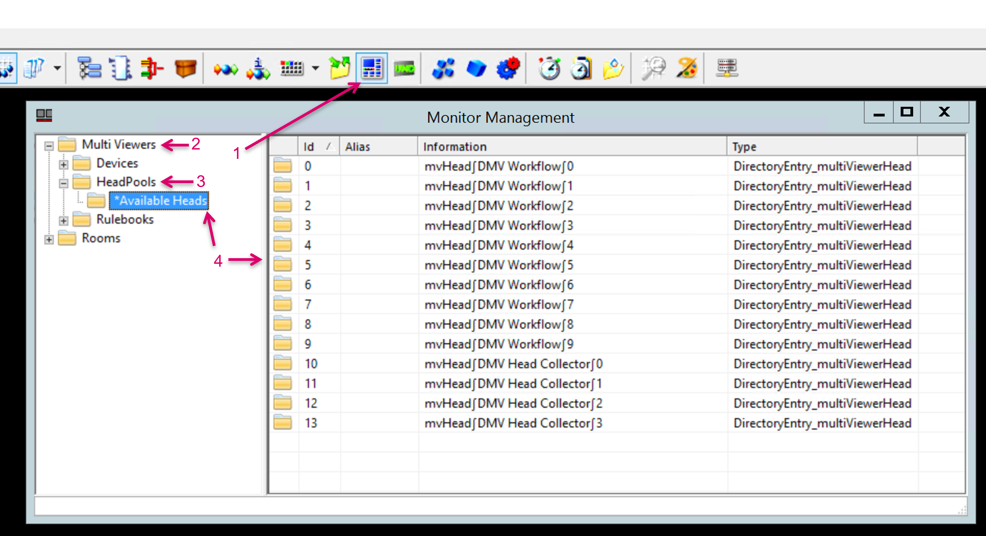
Navigate to the Monitor Management section from the vsmStudio toolbar (1), expand folders Multi Viewers (2) and HeadPools (3). Open folder *Available Heads, where all physical DMV Heads are listed, as read-out by the module. The folder *Available Heads is basically just the master repository, from where Heads can be assigned to operational pools via drag & drop. Therefore, we first need to create one or multiple operational HeadPools.
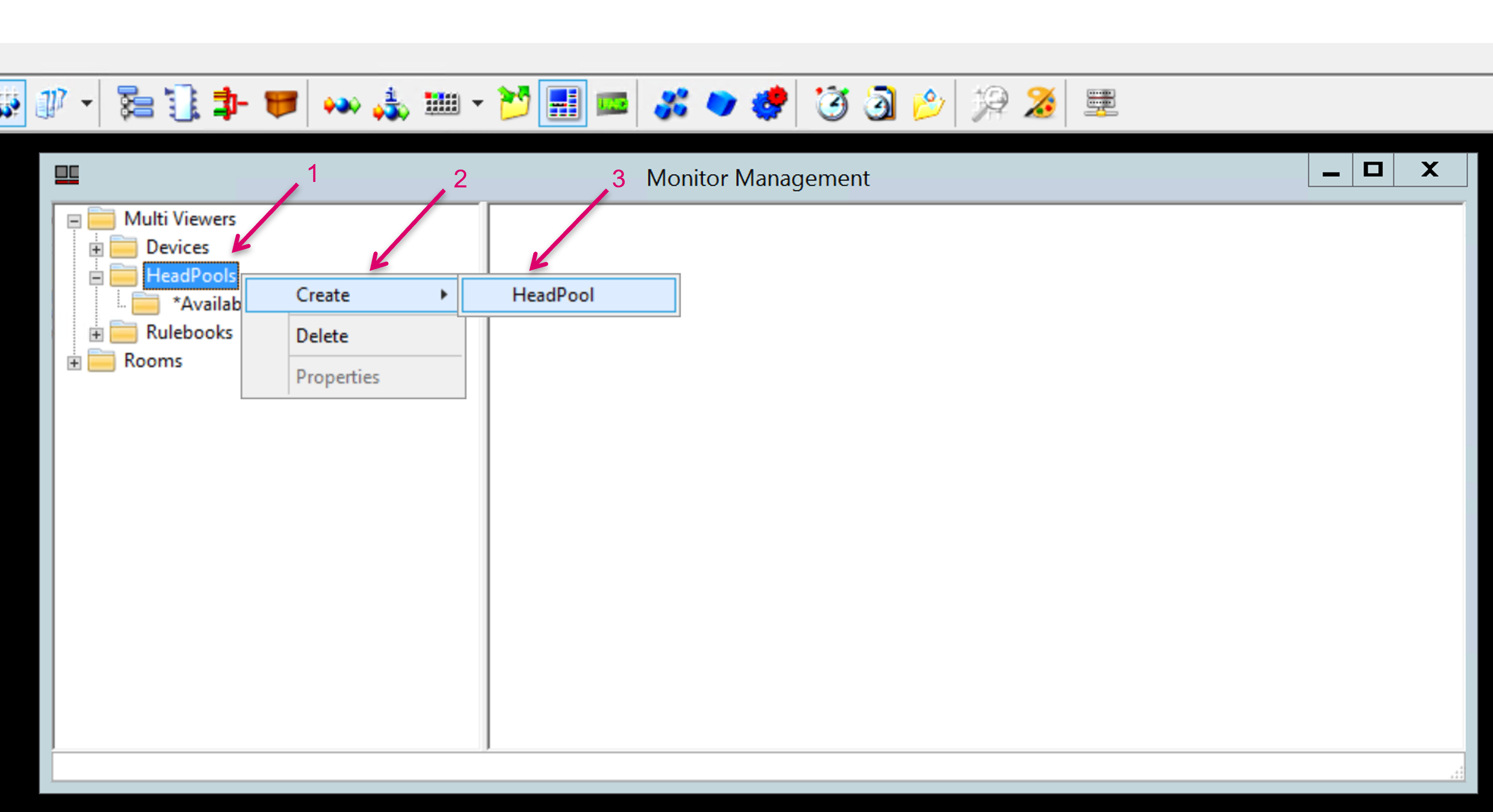
To create a HeadPool, right click on HeadPools (1), Create (2), HeadPool (3).
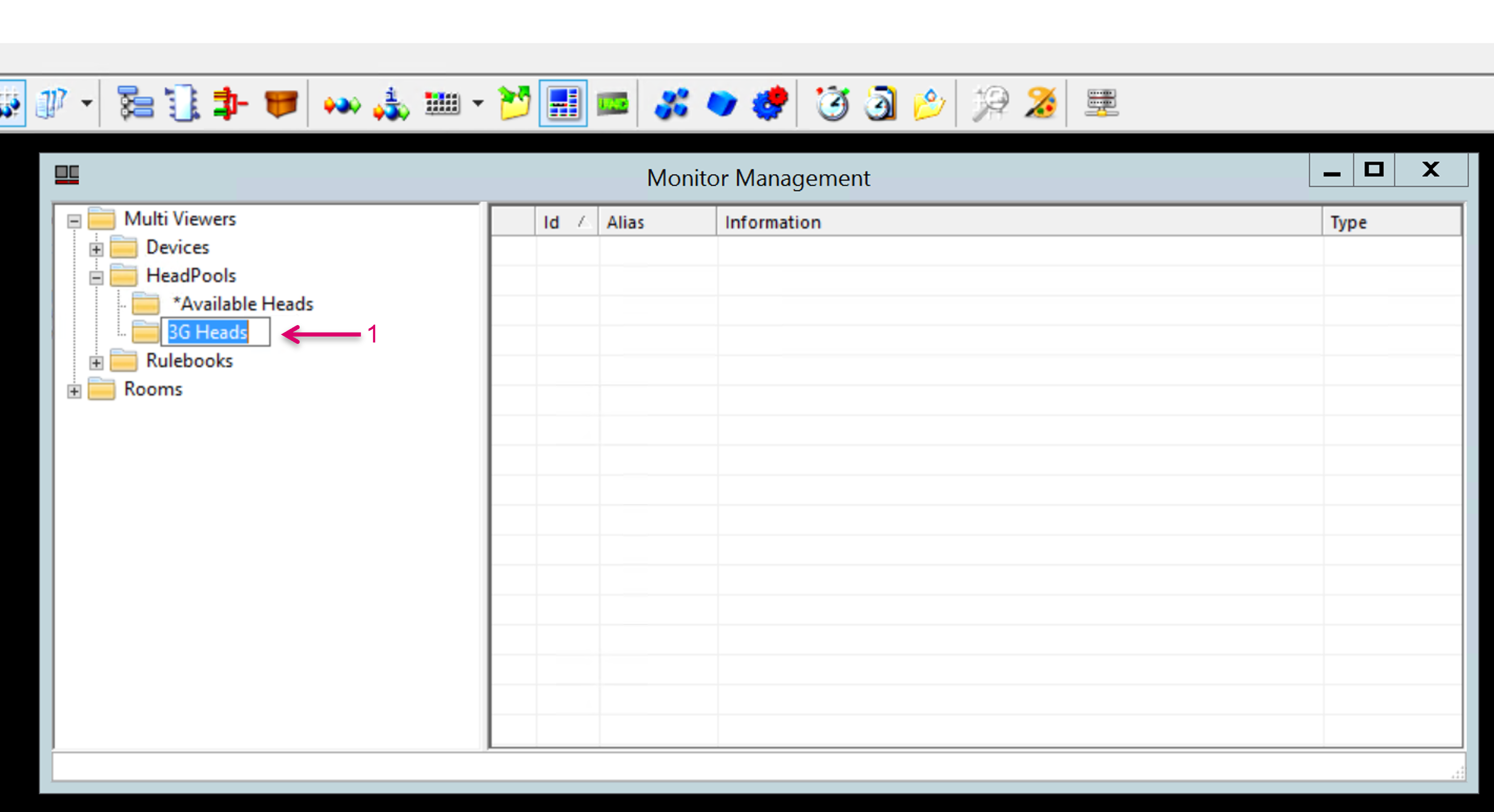
A possible application for a HeadPool is to group DMV heads of different formats e.g., in a setup with both, 3G and UHD heads and respective monitors. Label the created HeadPool accordingly.
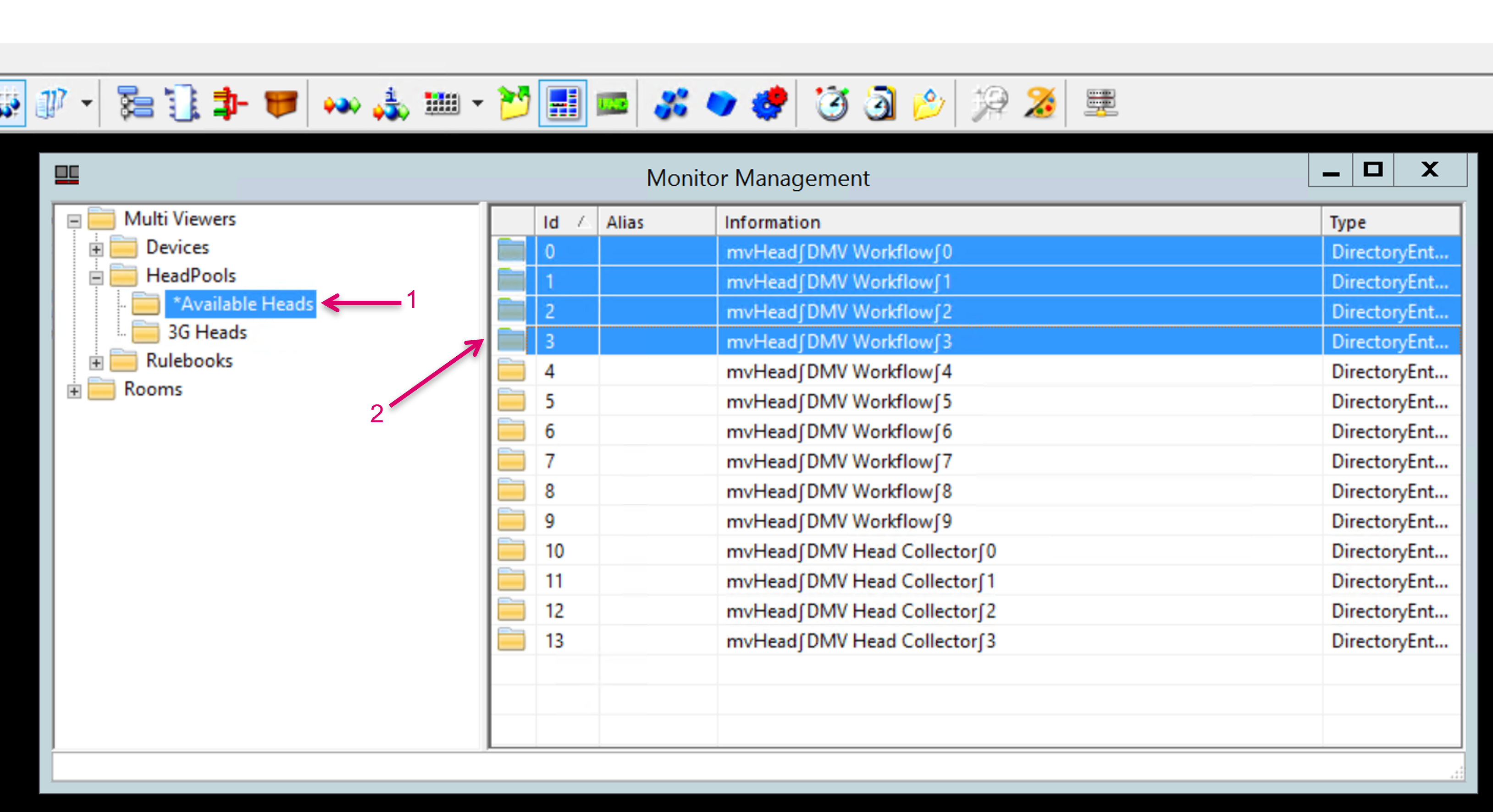
To assign heads to a HeadPool, open the folder *Available Heads (1), select the desired heads (2), and drag & drop them onto the respective HeadPool folder (3).
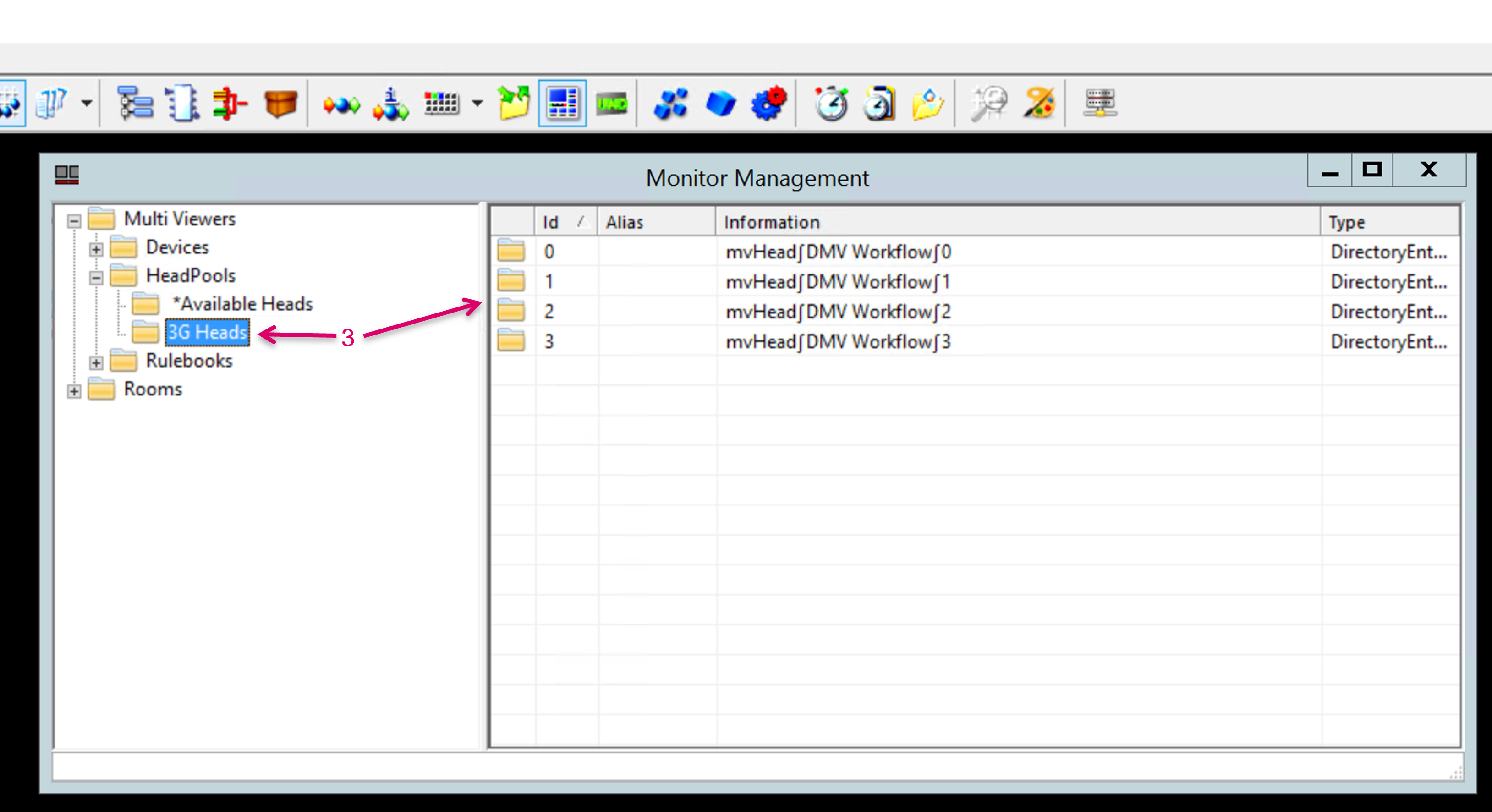
Another possible application for a HeadPool may be the logical separation by location (1). DMV heads can be assigned to multiple pools (2).
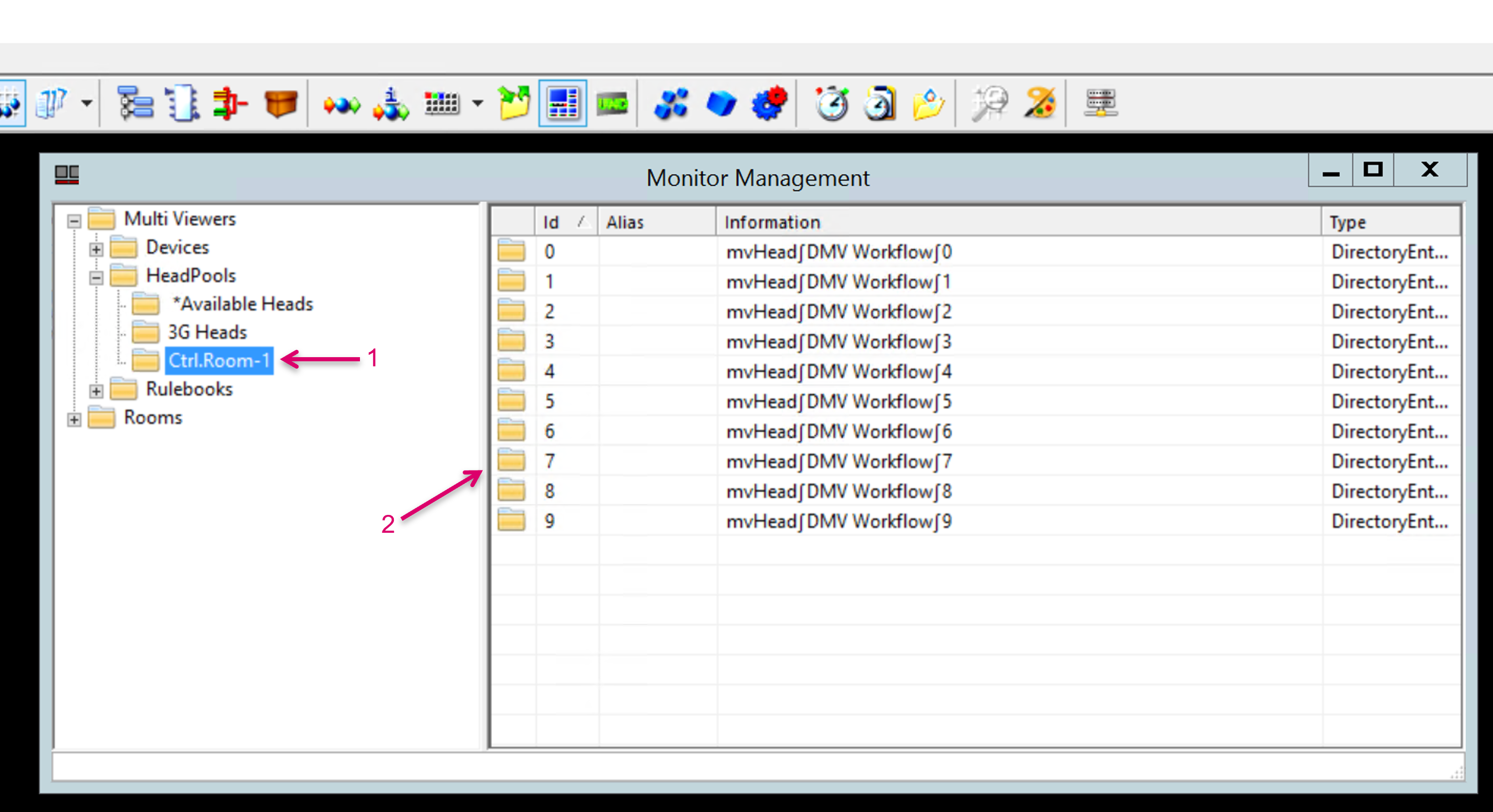
Assign HeadPool to Signalpath targets
In the next step you need to define per monitoring target (endpoint that should be able to utilize a multiviewer head) from which HeadPool it should be served. Create a new, or open the Properties window of a respective Network Target Signal Path (1). Navigate to Attributes (2) and select a HeadPool from the pull-down menu next to Has Access to Head Pool (3).
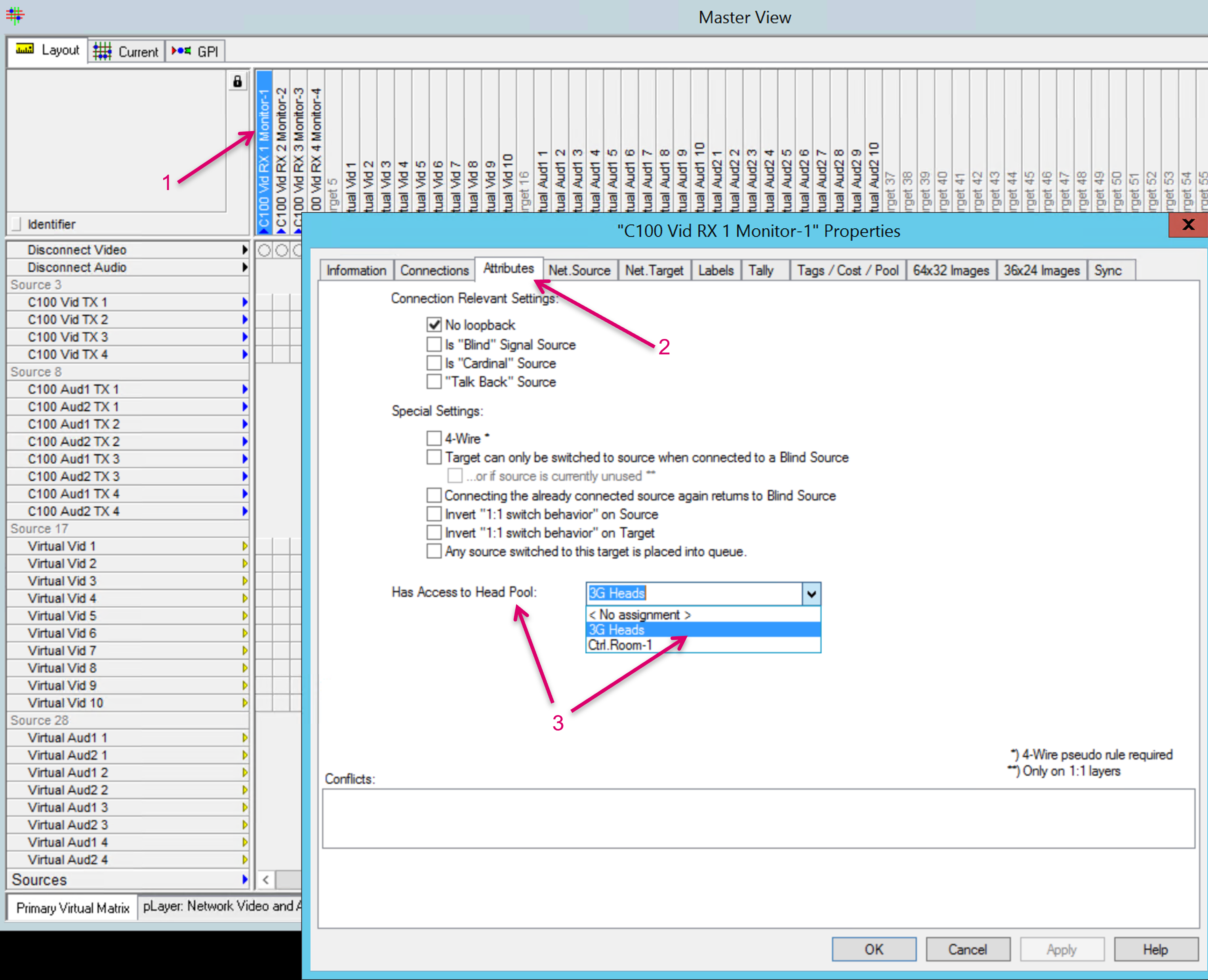
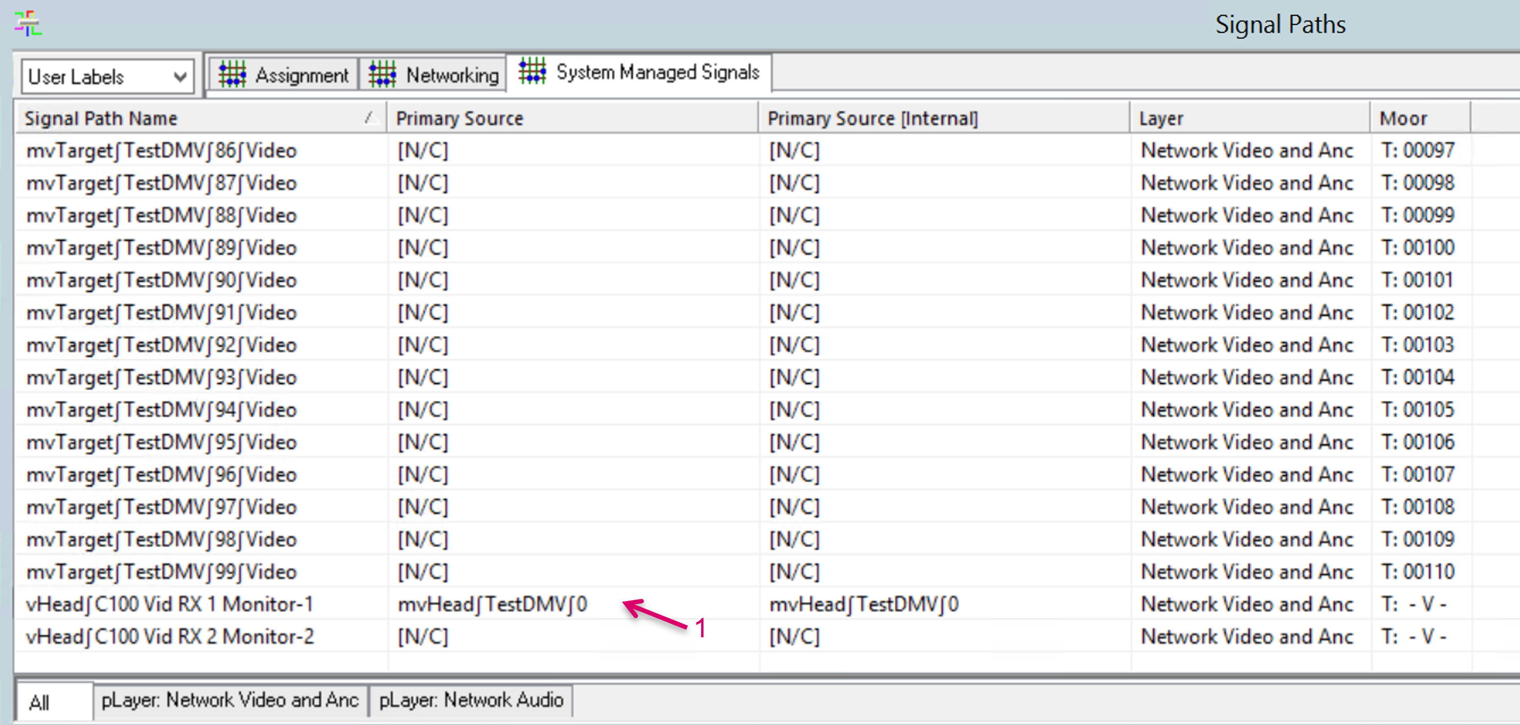
As a result of this assignment, the VSM system will create one more System Managed Signal path. This time a Virtual Head instance is created for each target that got a HeadPool assigned. Each vHead belongs to one specific target and is displayed accordingly as part of the vHead Signal path label (1).

The concept of the virtual Head (vHead) Signal paths allows for a dynamic usage of physical heads (pool concept), still providing a dedicated source per monitoring target that can be switched to, no matter which physical head the system will choose from the pool. It also allows to switch a monitoring target to any direct network source and get back any time to its dedicated multiviewer head layout. Although the vHeads are dedicated and owned by one specific target when it comes to layout and PIP assignment, the vHeads can be used as usual network sources which allows other users/ targets to monitor the same multi viewer layout as the original user/ target.
The allocation of physical to virtual head is done automatically by the VSM system, the first time a layout is requested (by button push, please refer to chapter Panel Configuration) for a monitoring target. The current assignment is displayed in the Signal Paths view (1).
Only standard signal path network targets are supported. No involvement of Tielines on the monitor target side!
Panel Configuration
In the panel editor of vsmStudio, assign Network sources and Network targets (with Head Pool assigned) to buttons on a panel page (1). The Distributed Multi Viewer module comes with a new special function key, named Multi Viewer (2). Assign a couple of buttons with this special function key (3).
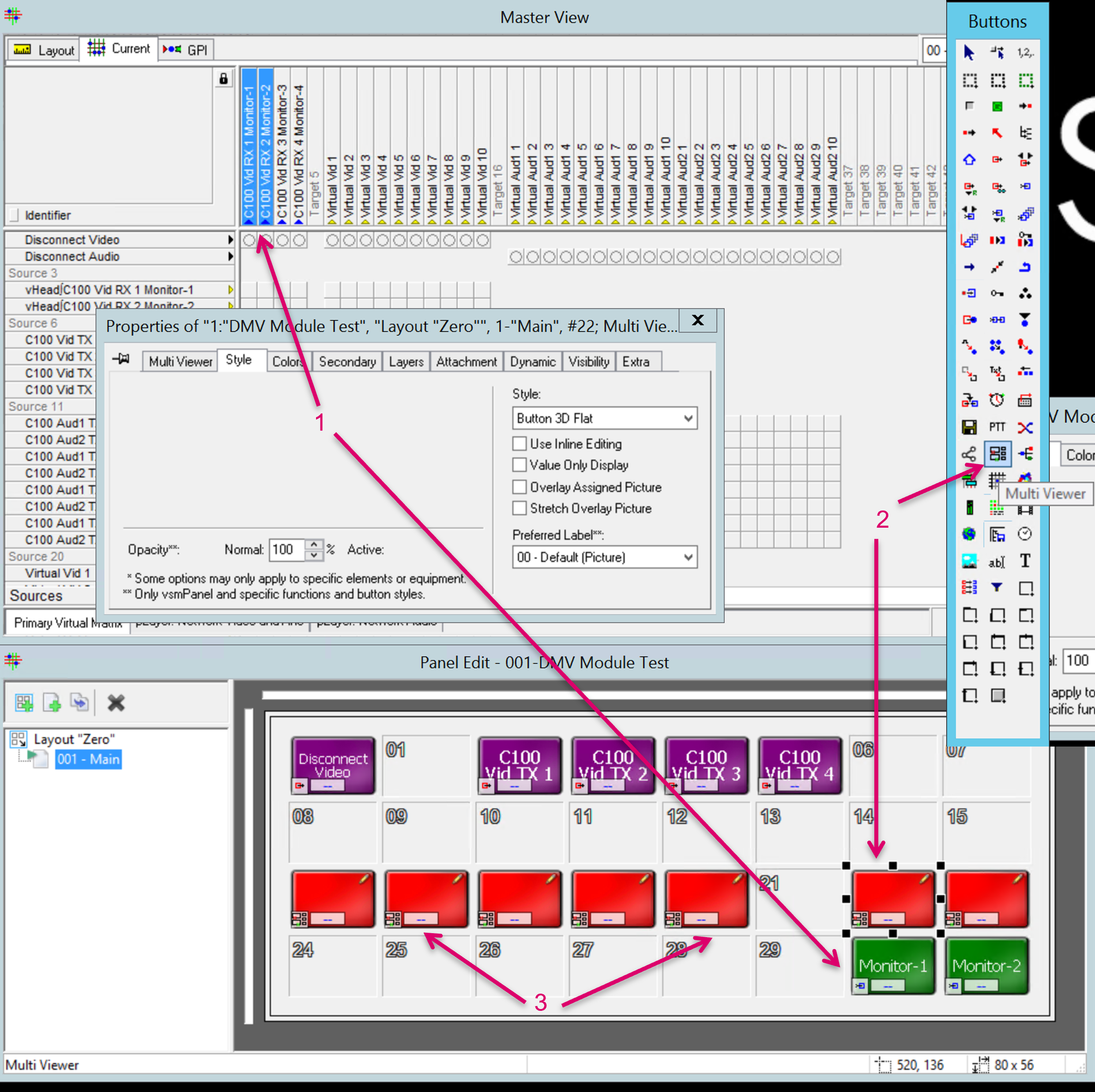
This new button type has multiple, selectable functions, as described in the following. Without any further assignment or configuration, any of these Multi Viewer buttons will act as PIP target button that get dynamically assigned based on the selected target (with an active head assignment). That said, to be able to switch between any direct network source or the DMV head output, two buttons on the panel must act as On and Off switch. To assign these functions, select one of the Multi Viewer buttons (1) to open the Properties window. Navigate to the Multi Viewer tab (2). Assign one button on the panel with the On function (4), and another with Off.
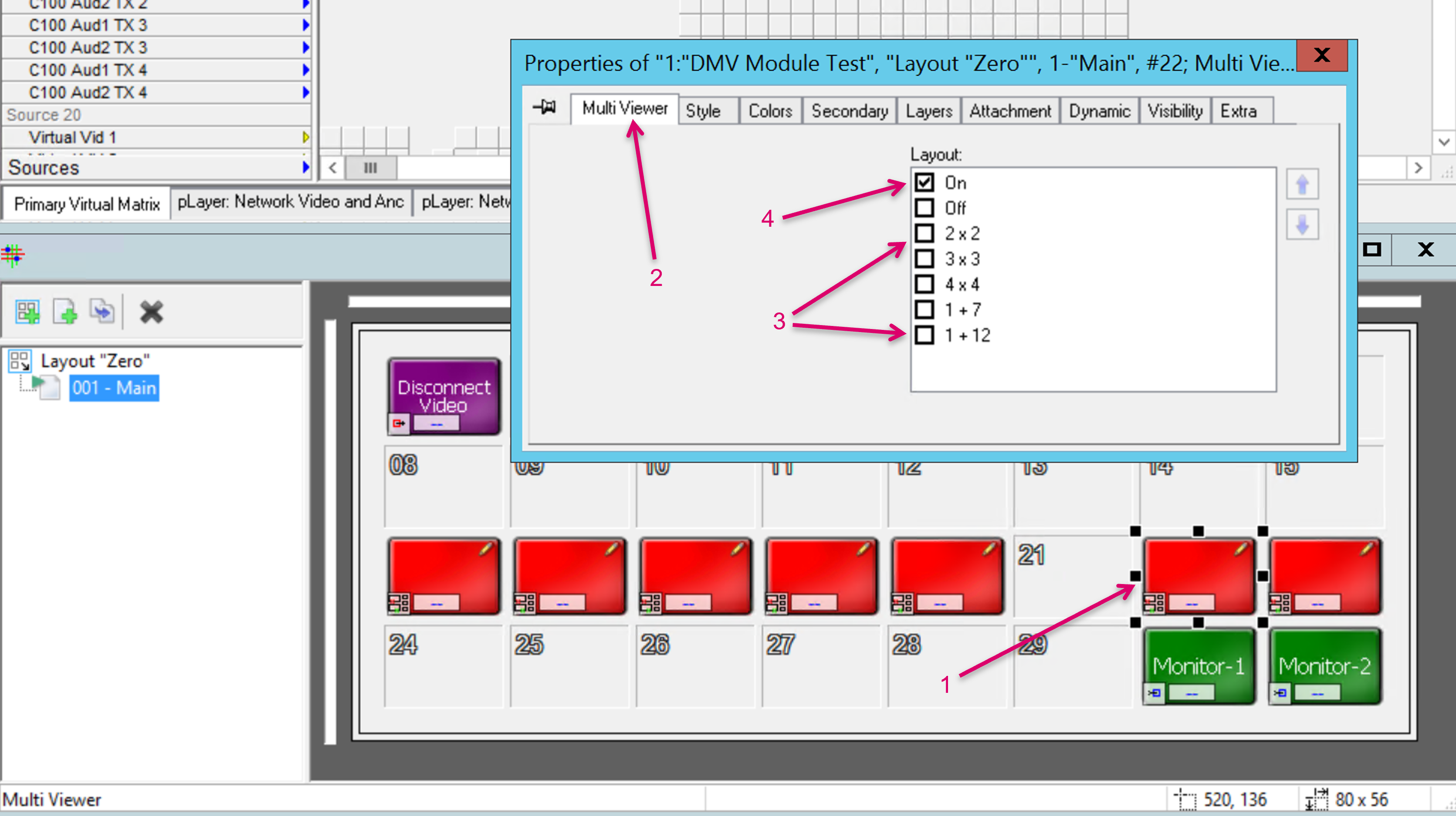
The other selectable functions in this section (3) would allow to assign a predefined PIP layout recall to a Multi Viewer button. Since there is no possibility to modify the underlying layouts and there is no plan to extend this list, we currently recommend the usage of theWall as the one and only tool to create, save and recall layouts. The predefined layout recalls via the DMV module may be used for initial testing only. Do not use these recalls in parallel to theWall to avoid communication conflicts.
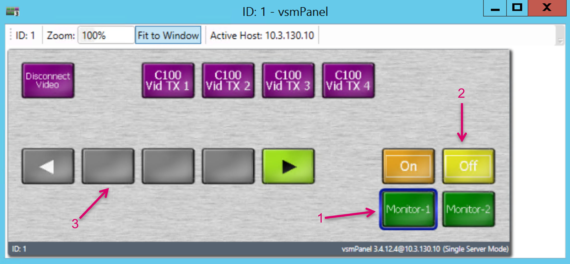
On the vsmPanel the buttons appear like this. If a monitor target is selected (1) while the function button Off is active (2), it means that no DMV head is switched to this target but any other source or blind. The PIP target buttons are greyed out (3).
If a monitor target is selected (1) while the function button On is active (2), it means that any DMV head is currently switched to this target (via the dedicated vHead of the selected target). The PIP target buttons are active (3). The brackets around the PIP number show if a PIP ID is currently enabled or disabled in the current layout of the DMV head. In this example only a two-PIP-layout was recalled on the respective head.
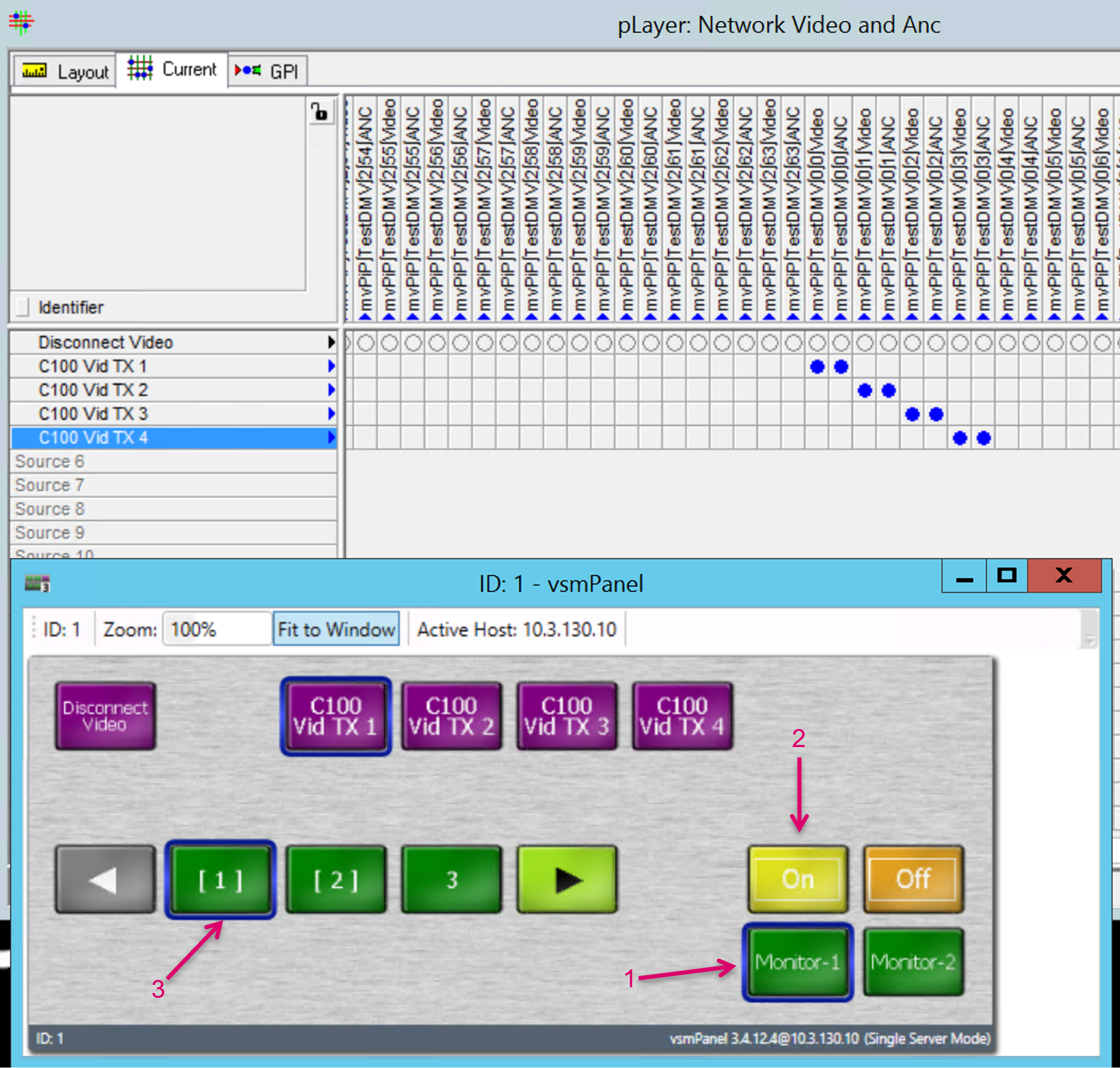
The PIP targets on the buttons represent the physical PIP targets of the currently assigned head, no matter which physical head was assigned to the virtual head (vHead) of the selected target, the PIPs will address the correct target. Whenever the button Off is selected, the selected target will be assigned the last known, previous network source.
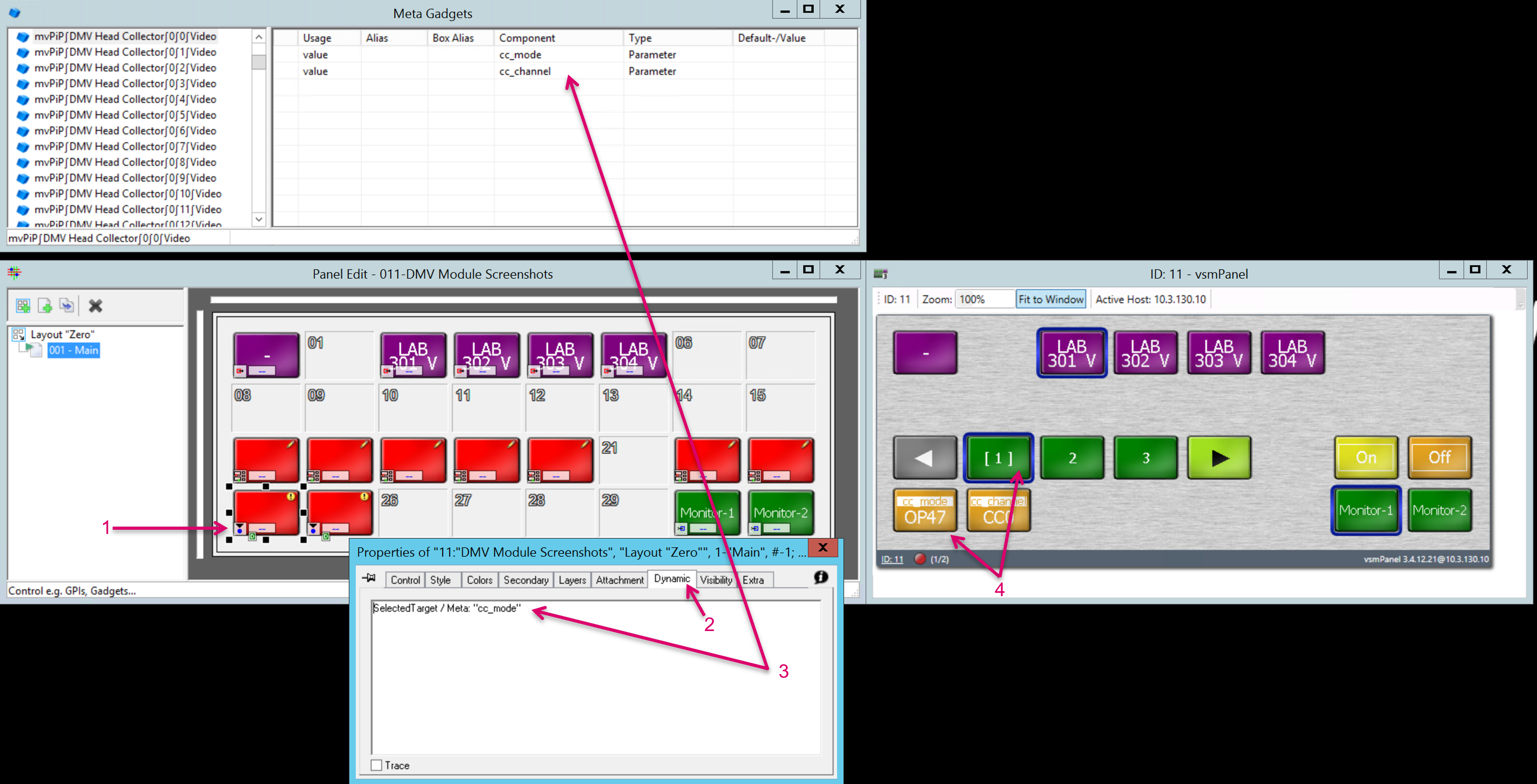
Due to the dynamic Head allocation and in order to access PIP related Closed Caption parameters from a panel, the respective parameters must be dynamically assigned to buttons via DAS. To do so, open the respective panel in the editor view and assign the Control Button Function to any of the keys (1). In the Button Properties window, navigate to the Dynamic tab (2), and enter an appropriate script, e.g., {SelectedTarget / Meta: "cc_mode"} (3). Following a PIP target selection, the so configured button will then be assigned with the respective parameter (4) and can be operated accordingly.
Store and Recall PIP assignments via Storage groups
Navigate to Storage Groups via the vsmStudio toolbar. Right click on Roots (1) and select New Folder (2). For better transparency, rename the folder according to its dedicated usage (3).

Drag & drop one or more respective Monitor target(s) (1) on the Storage folder (2).

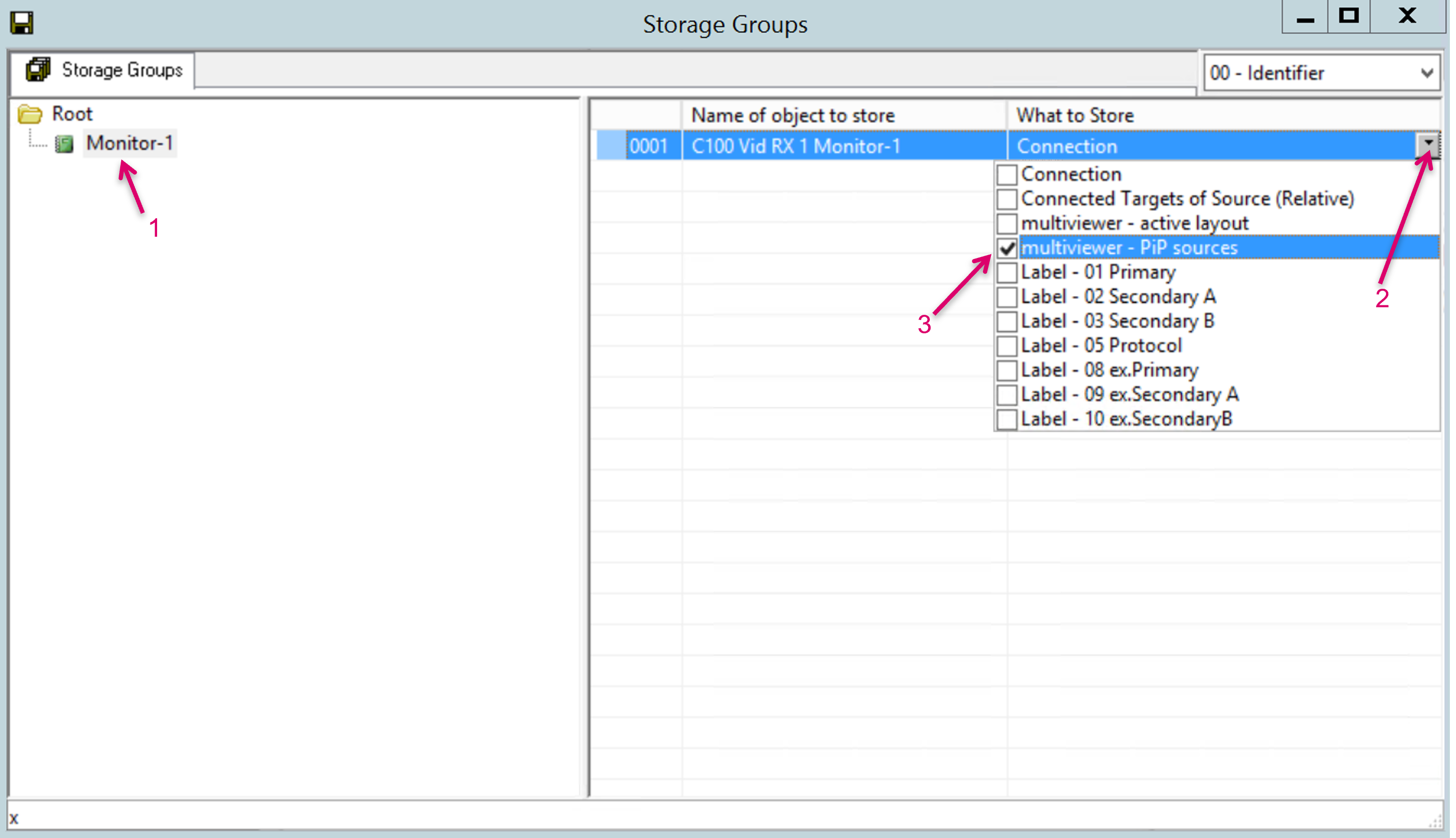
Select the Storage folder (1), open the drop-down menu next to the Monitor target (2) and select multiviewer – PIP sources (3).
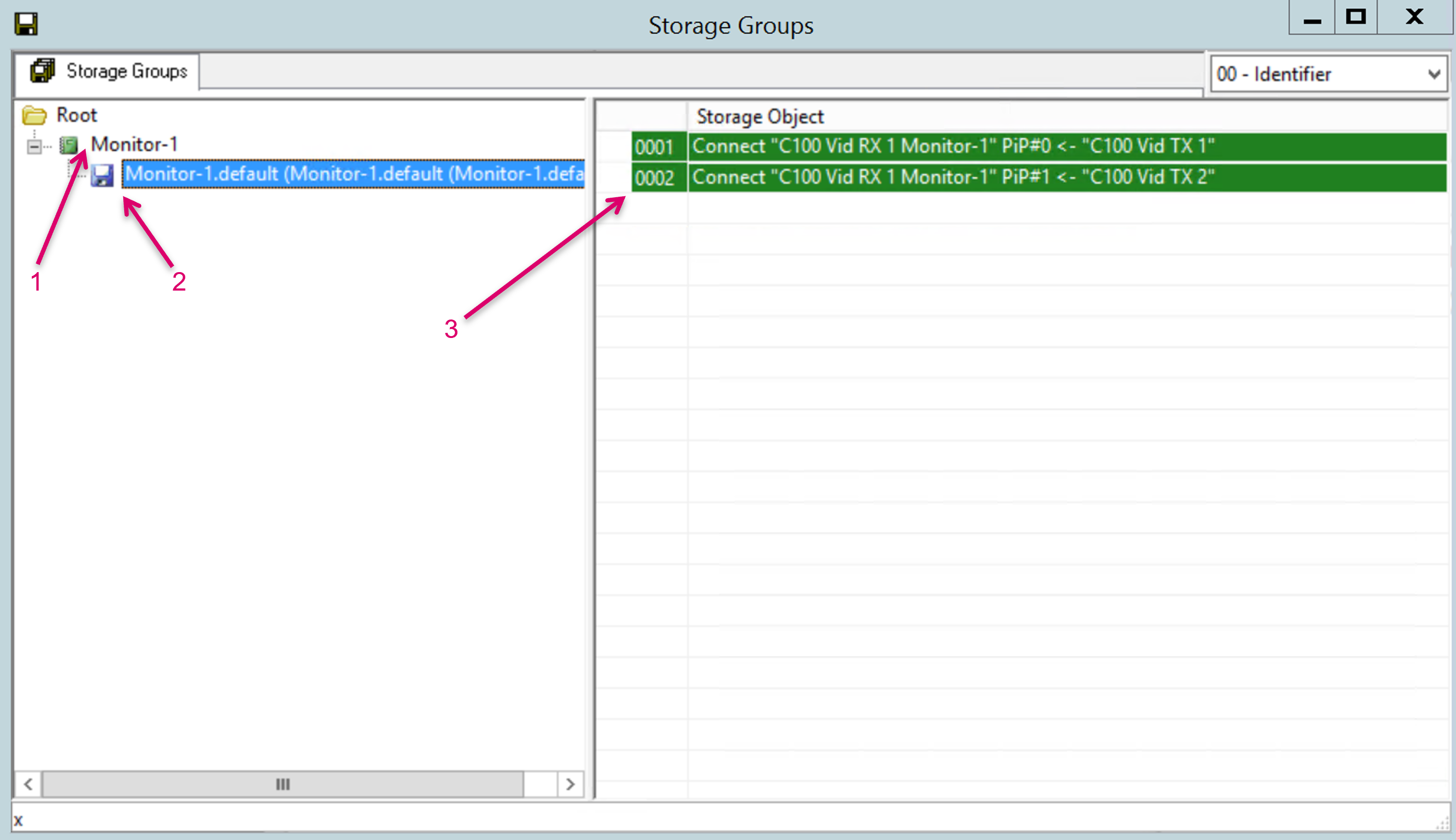
Right click on the Storage folder (1) select Save. A Storage disc is created (2) that contains the current PIP routing to active PIPs (3).
Only the routing state to currently active (enabled) PIPs will be saved. Means, if the current active layout would have contained 64 PIPs at time of Save, we would also see this as stored status in the Storage Disc. This dynamic behavior may need additional attention when building save/recall workflows.
Special Label Handling
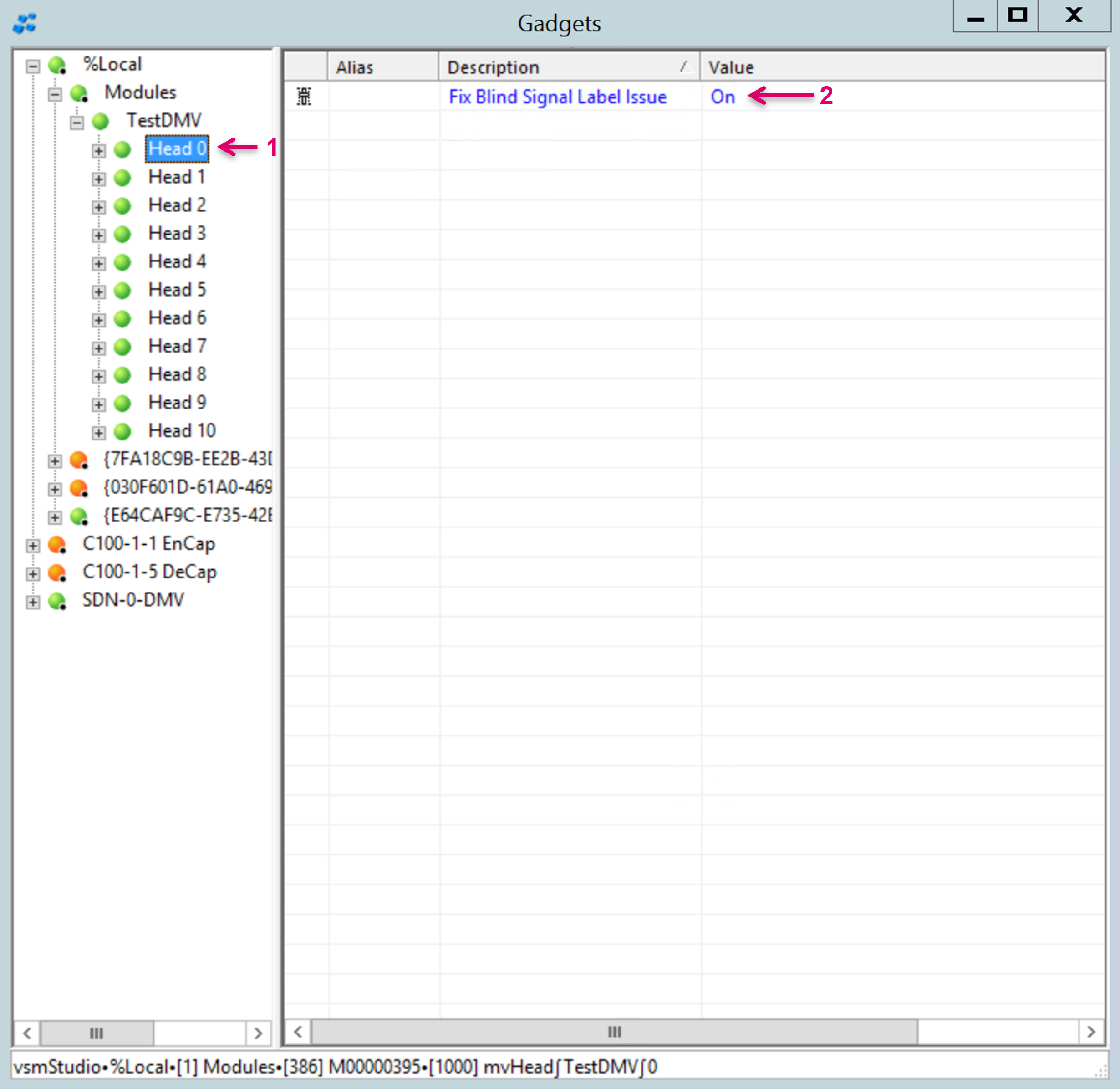
There are multiple label related settings in the DMV that allow to select Label sources for areas of displayed text, like UMD Cells of a PIP. For dynamic labelling, the Distributed Multi Viewer module always addresses Monitoring Object Cell 0 which is then forced to be set as Label source of PIP UMD Cell 0. In this regard, there is one specific Source to PIP assignment that requires a special handling though. If Blind/Disconnect is selected as PIP Source, no Monitoring Object is used inside the DMV, therefor, no Label source is present for the PIP UMD and no Label would be displayed. Only in this specific case, VSM changes the Label source for the PIP UMD Cell 0 to the local PIP label to display a Blind label. Once a valid Source is again selected for the PIP the Label source will be set back to Monitoring Object label. Now, there is one application scenario that requires that VSM does NOT force/ control the PIP UMD Cell 0 Label source. This is the case, when it is required that Cell 0 is statically assigned with a different Label Source, e.g., one of the Monitoring Object User Labels. For this workflow it is possible to disable the so called “Fix Blind Signal Label Issue” function per DMV Head. To do so, navigate to the Gadgets window/Local%/Modules and open the respective DMV node. Select the desired Head (1) and change the Value accordingly. The default value is “On” (2).
