vsmStudio - HOME Interface

Introduction
This chapter describes the interface between vsmStudio and HOME, Lawo’s management platform for IP-based media infrastructures. The interface via “HOME API” gives immediate access to all discovered and registered devices within HOME and allows for direct stream routing as well as control of all exposed device parameters. Furthermore, the implementation allows for system assisted configuration steps.
Best practice and known limitations:
- Connecting multiple HOME cluster with one vsmStudio system, currently requires to disable the “Prioritize Native Home Routing” option on the respective network layers.
- While connecting multiple vsmStudio Systems with one HOME Cluster is technically possible, this scenario is currently not recommended. Aside the expected increased data traffic, the handling of resources requires extra caution. Accessing the same resources, especially targets, from multiple control systems may lead to workflow conflicts and non-transparent status, since the actual HOME crosspoint state is currently not shared across such system topology. Disabling CPC for any shared HOME target would be mandatory.
- While HOME itself also provides a Stream routing UI and access to all device parameters, parallel routing operation from VSM and HOME is currently not supported. Stream routing via the HOME UI will not trigger flow routes in conjunction with a SDN and even in IGMP networks may lead to routing issues or inconsistent status display on any side.
- Aside the current technical restriction listed above, the HOME Stream routing UI gives access to physical resources only. Possible virtual abstraction layers (e.g. Virtual Signals) within the broadcast controller system will be bypassed if routing on physical essence level. Therefore, a parallel operation via broadcast controller and HOME UI may anyway not fit the most common application workflows.
Connect to a HOME Cluster
While it was and is possible to connect to each physical HOME Server directly, this is not the most efficient way to interface. Therefore, with vsmStudio release 26.1.1, we introduced a new method to interface to a HOME cluster, via a local NATS Leafnode Server, that runs on each vsmStudio Cluster Server. The connection is then established via one single connection between vsmStudio and the local NATS Leafnode while the NATS Leafnode Server itself connects to and communicates as part of the HOME cluster.
Further information on how to set up the HOME connection via the local NATS Leafnode Server, please refer to the specific documentation section in vsmStudio - Communication Port Management
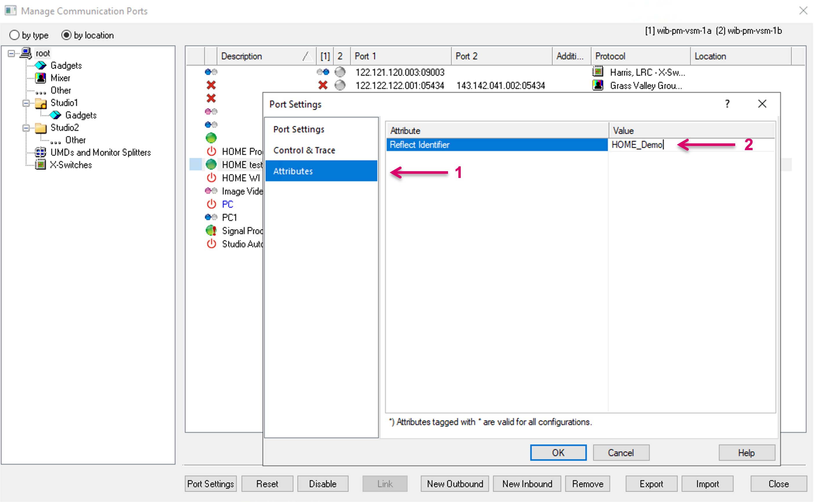
Before proceeding with the configuration, make sure a Reflect Identifier is set. Navigate to the Attributes sub-menu in the Port Settings (1) and set a Reflect Identifier (2) to clearly identify this HOME Cluster in the system.
After successful connection to a HOME Server cluster, all registered HOME devices, are listed in the HOME dialogue and Signal/Stream resources can be configured from there. In addition, the Gadget tree will provide a respective HOME node, providing access to all parameter (GCF) controls of registered devices.
The HOME view and Device list
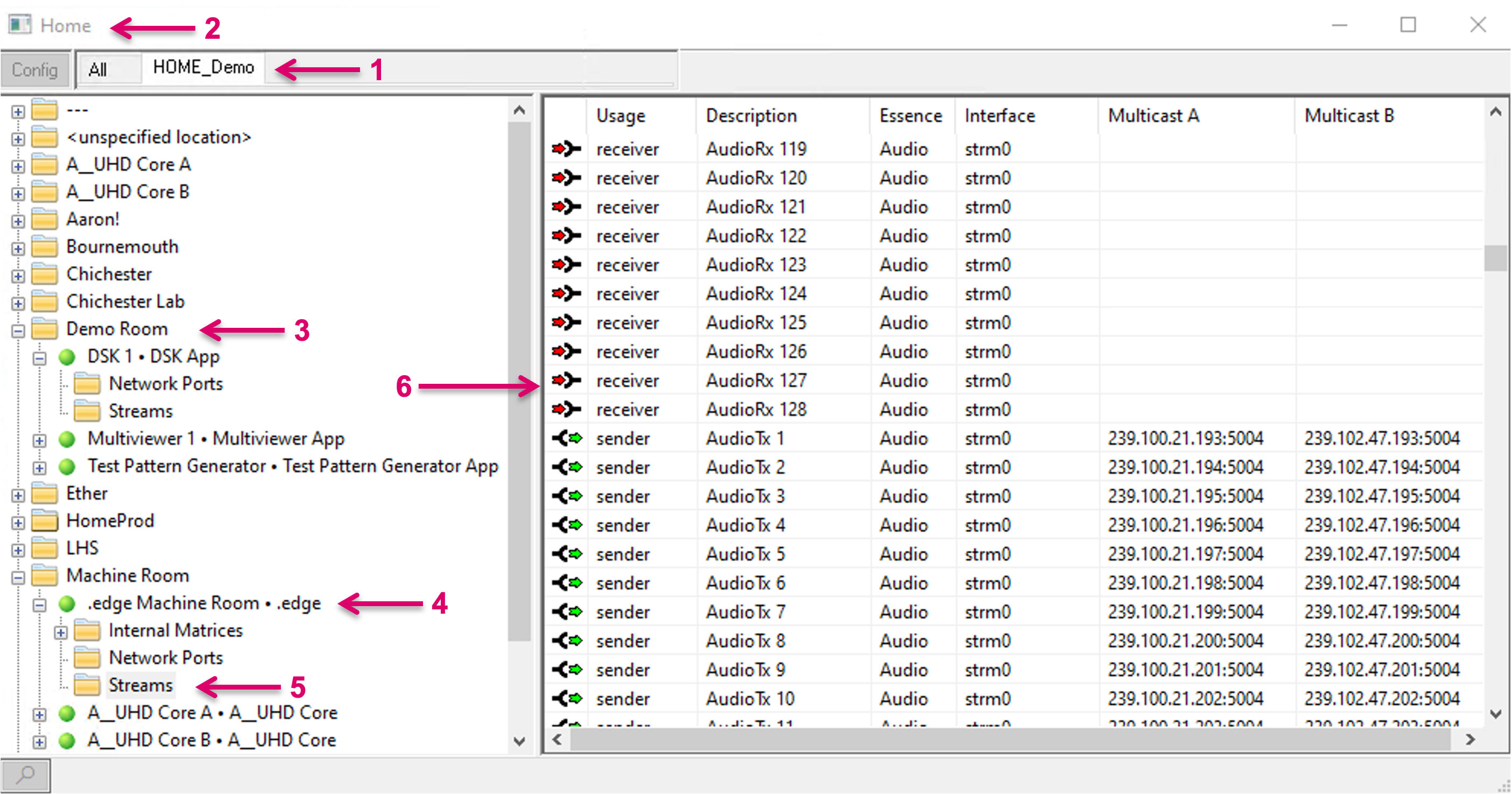
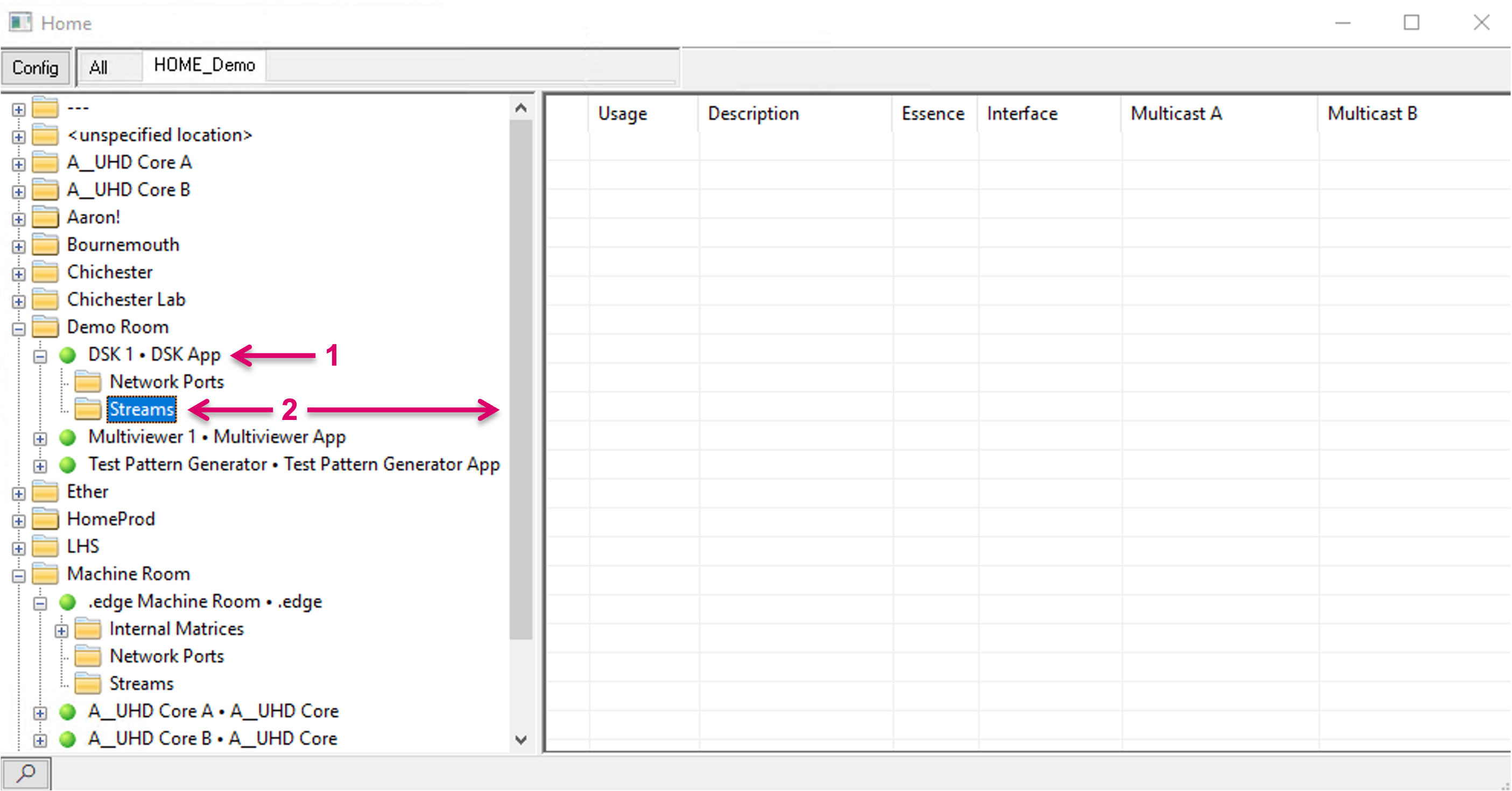
Once a valid connection to a HOME cluster is established, the respective HOME cluster is shown as tab (1) in the HOME view (2). All registered HOME Devices are listed in a Folder tree structure based on the HOME Location label (3). Each device (4) may be presented with a number of sub-folders, depending on the available resources (5), for instance, the folder “Streams” gives access to all Signal essences like Stream Sender and Receiver (6).
For reference, the HOME UI (1) with Devices list (2).
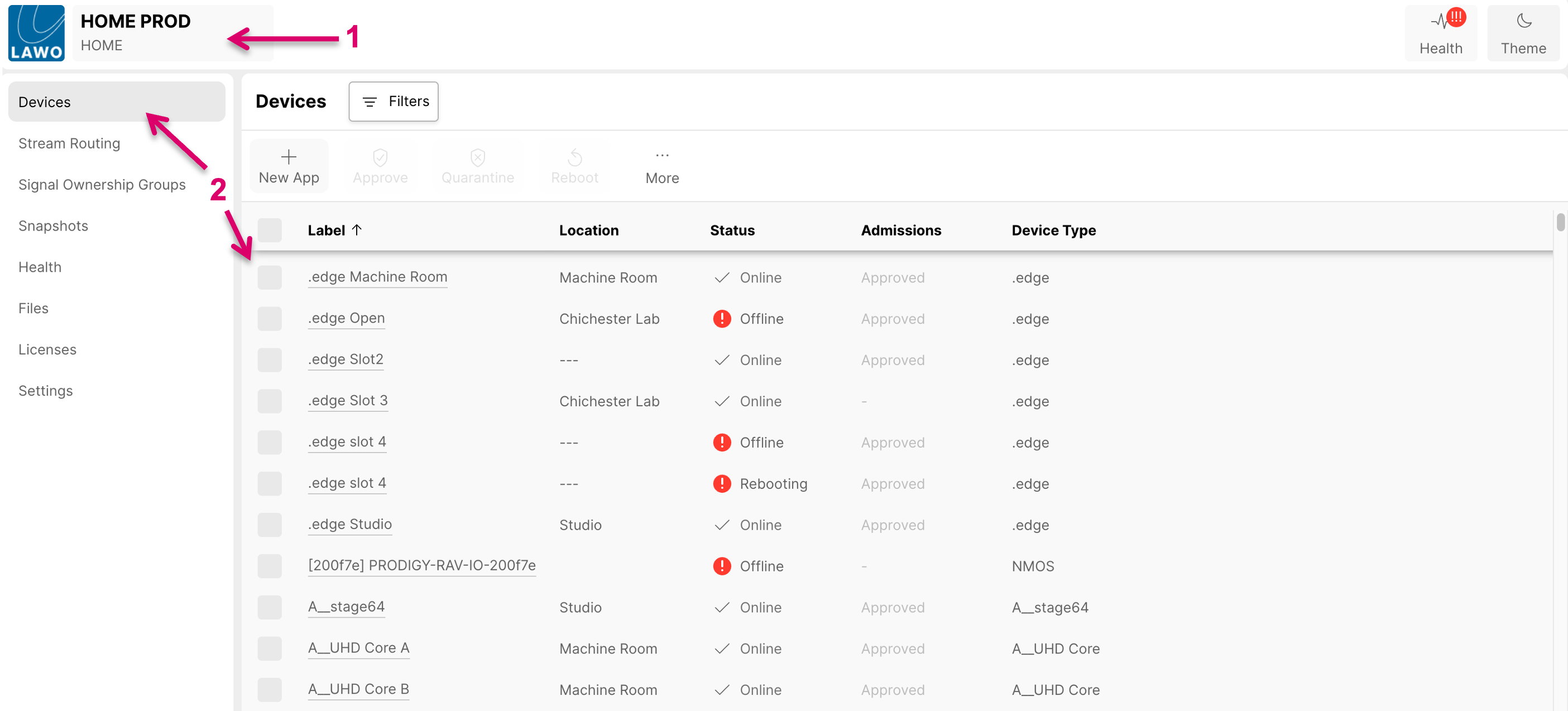
Devices may remain listed with a valid connection status in the HOME view (1), according to their existence in the HOME directory. Means, a HOME App that is created but possibly stopped, will still show as “online”, while no parameters will show and be accessible (2).
The HOME node in Gadget tree
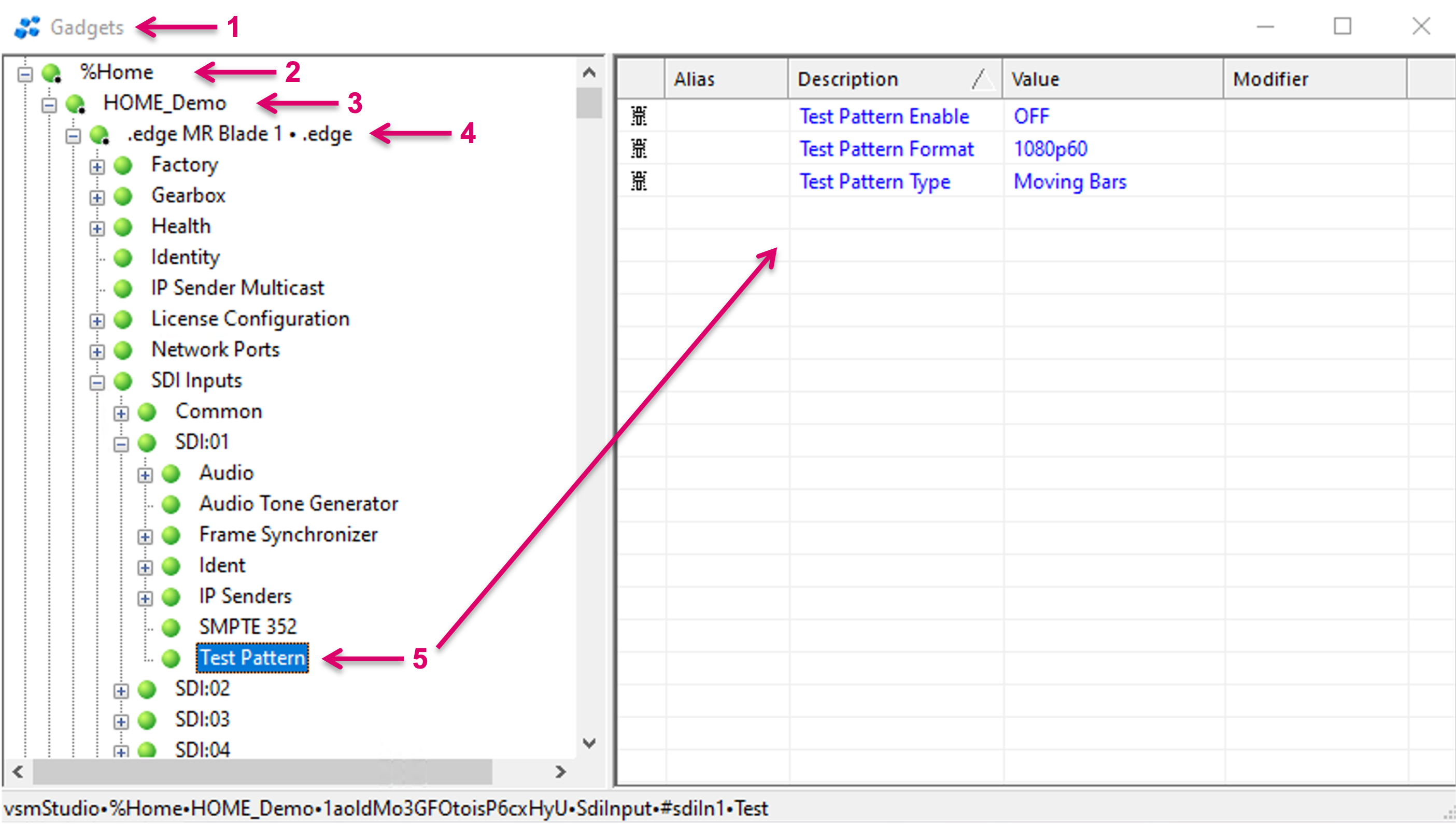
Navigate to the Gadget tree view (1). Once a valid connection to a HOME cluster is established, a %HOME node (2), and the connected HOME Cluster as sub-node, labeled with the defined Reflect Identifier Name (3) will show in the Gadget tree. Sorted by registered HOME Devices (4), the tree gives access to available parameter controls (5).
Config view
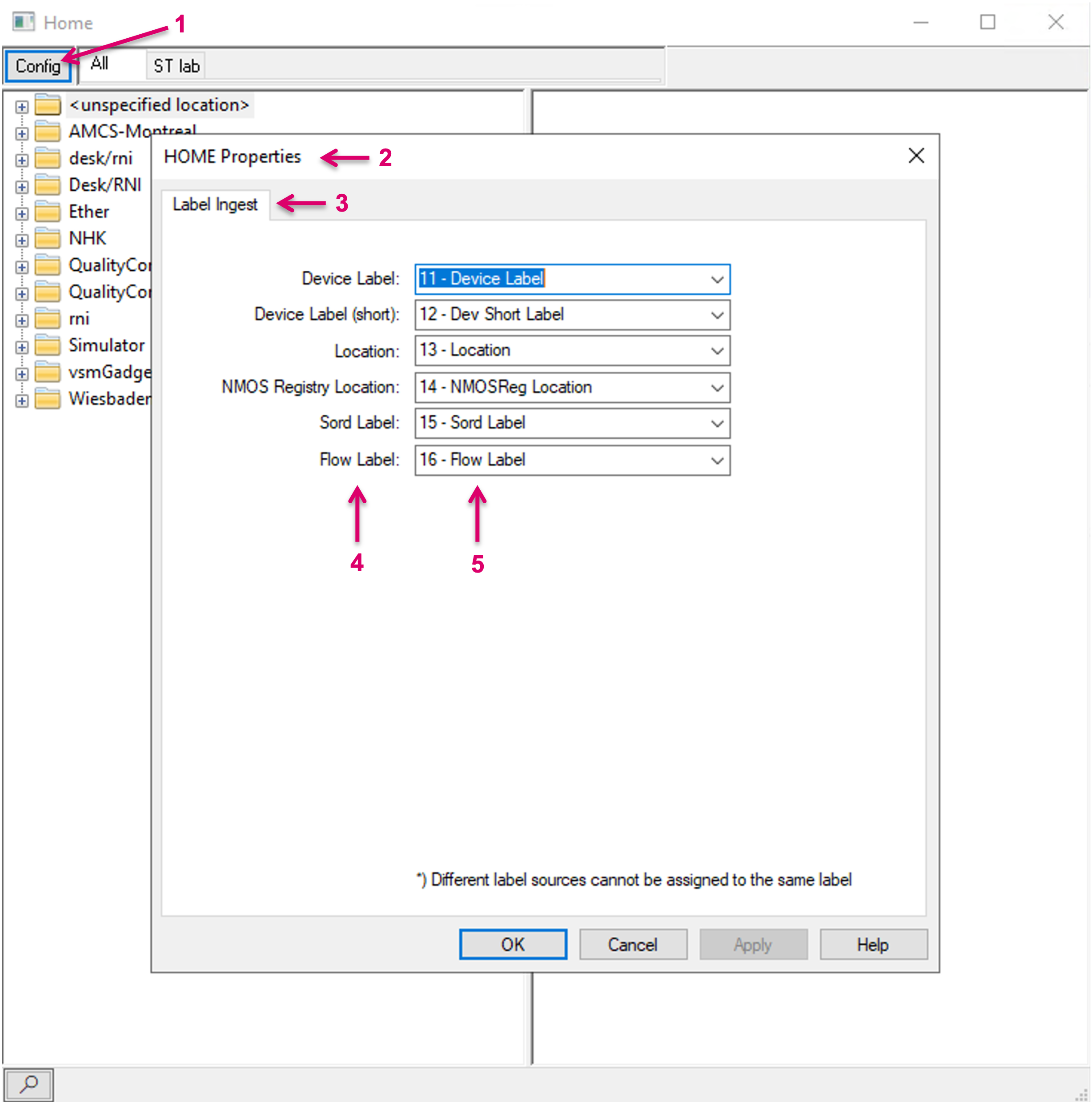
The system assisted creation of HOME resources within vsmStudio allows for selective label mapping with the same action. To map label information, exposed by HOME to respective label levels within VSM, navigate to the Config tab within the HOME view (1). In the HOME Properties dialogue (2) and the Label Ingest tab (3), the respective HOME label parameters (4) are shown alongside selection boxes (5) to map to the desired vsmStudio label level.
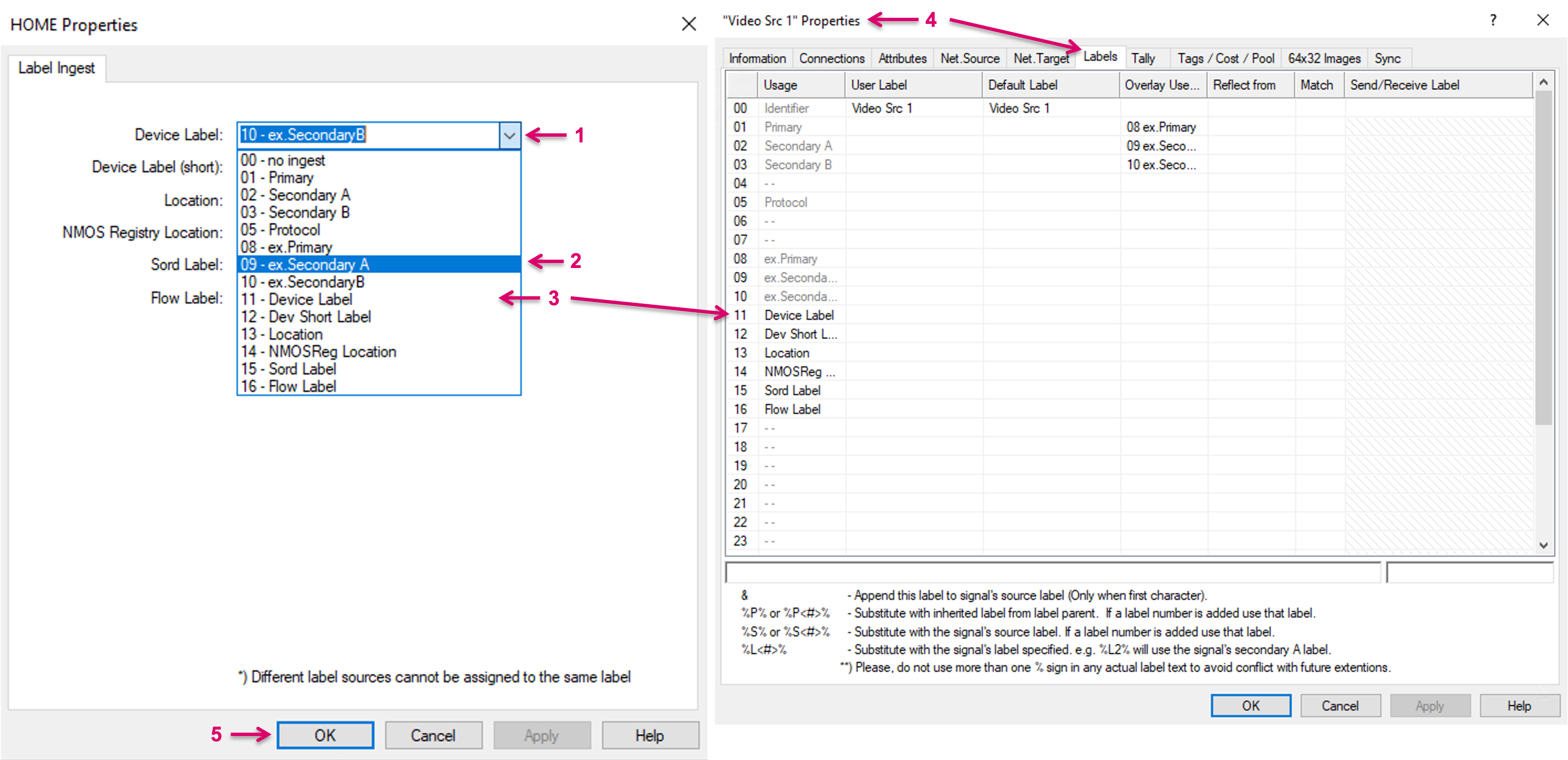
By click on the little arrow in any of the selection boxes (1) a drop-down list (2) shows all label levels with pre-defined Usage name (3). Make sure to have the desired label levels named beforehand via any Signal Path Properties dialogue/ Labels tab (4).
System assisted Network Signal Path configuration for HOME resources
For HOME devices and their Network Senders and Receivers, vsmStudio provides a system assisted configuration method that allows a speedy creation of Network Signal Paths. Pre-conditions are that Network Layers have been created already beforehand and that the respective Device is running and online (in case of HOME Apps, shall be started).
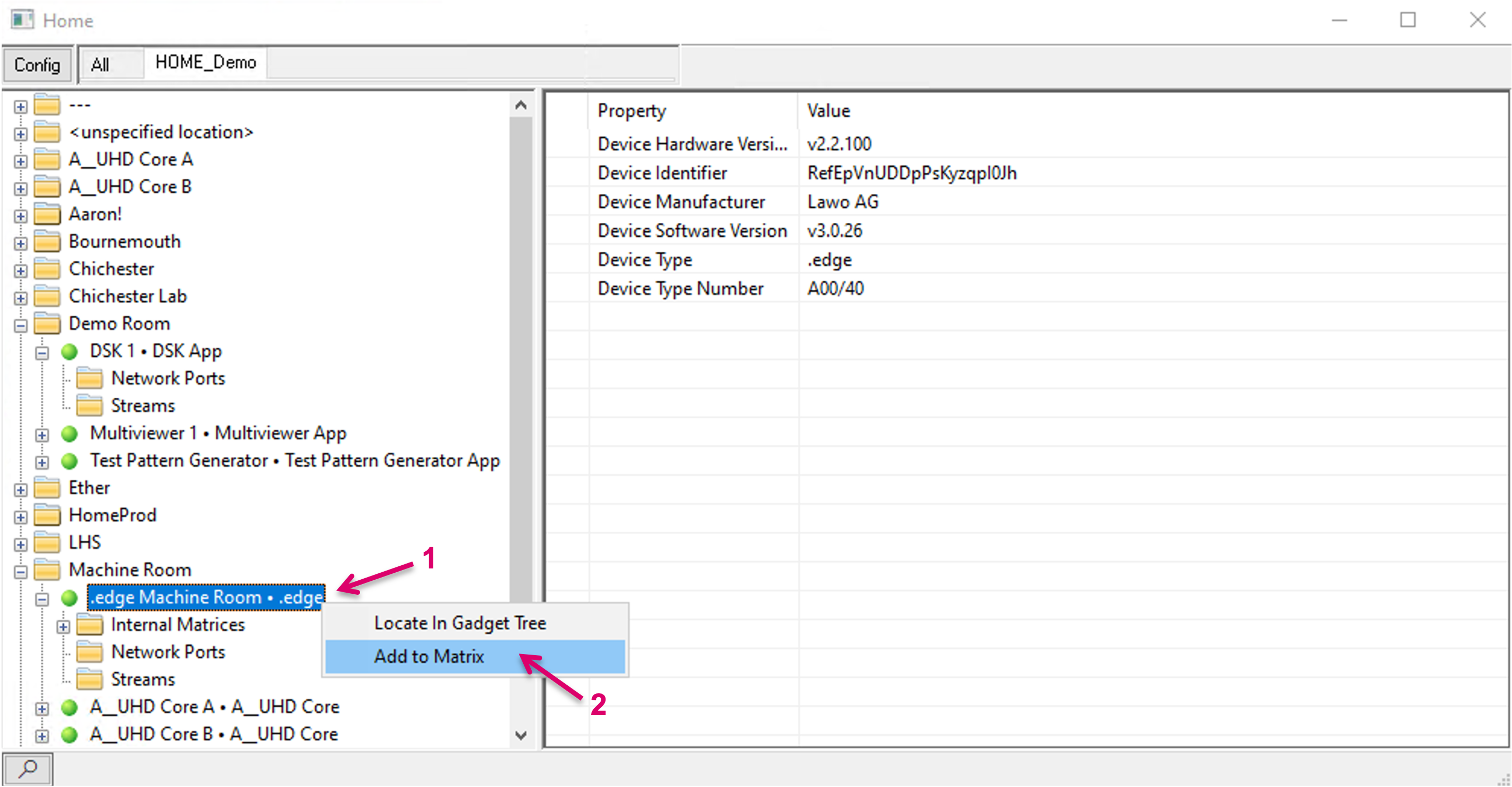
Navigate to the respective HOME device (1). Right-click on the device entry and select Add to Matrix (2).
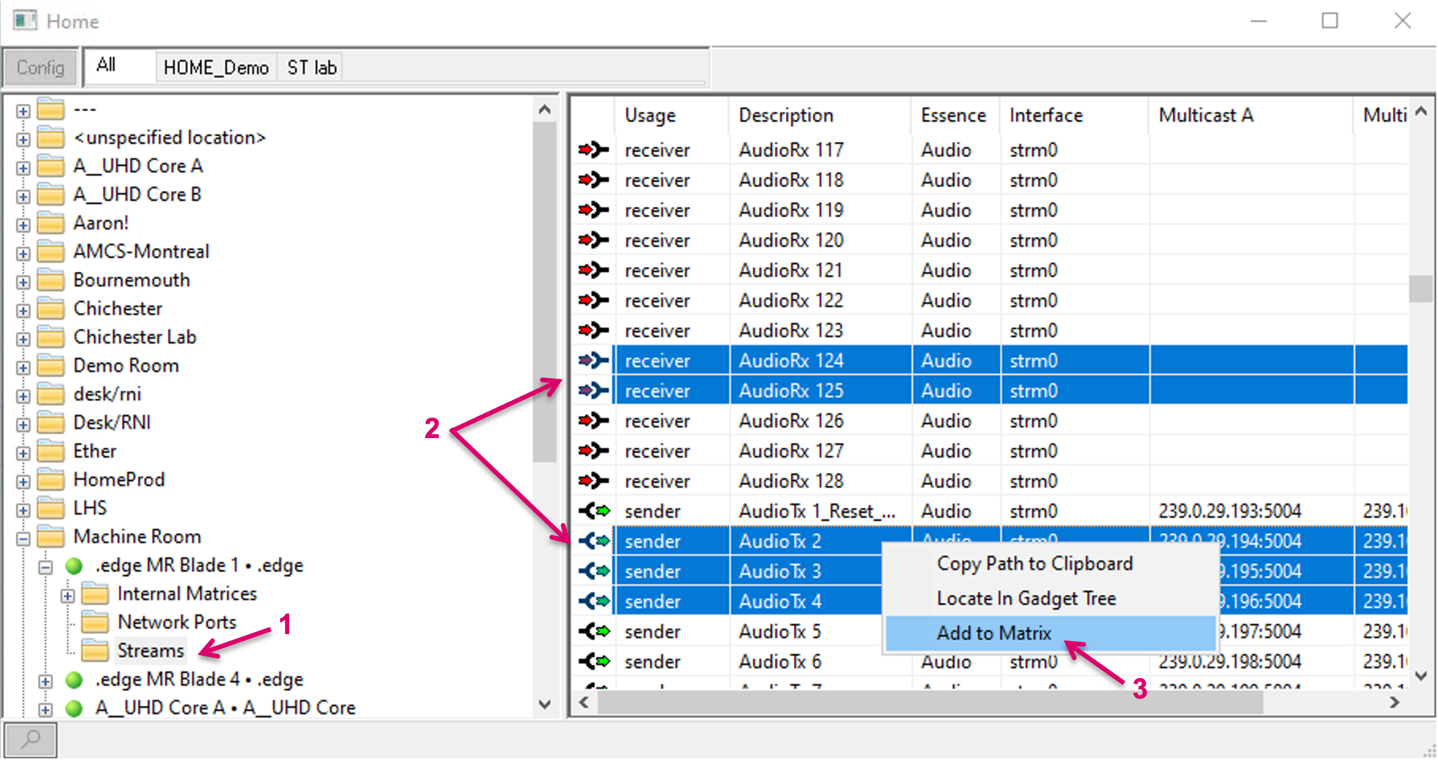
Alternatively, it is possibly to select only selected Sender and/ or Receiver resources. To do so, navigate to the Streams sub-node (1), select the desired resources (2), then right-click and select Add to Matrix (3).
In the following dialogue select to which Network layer the new Signal Paths shall be assigned. Select the respective Layers for Video (1) and Audio (2). Meta essences will follow the selection for Video. Confirm with OK (3).
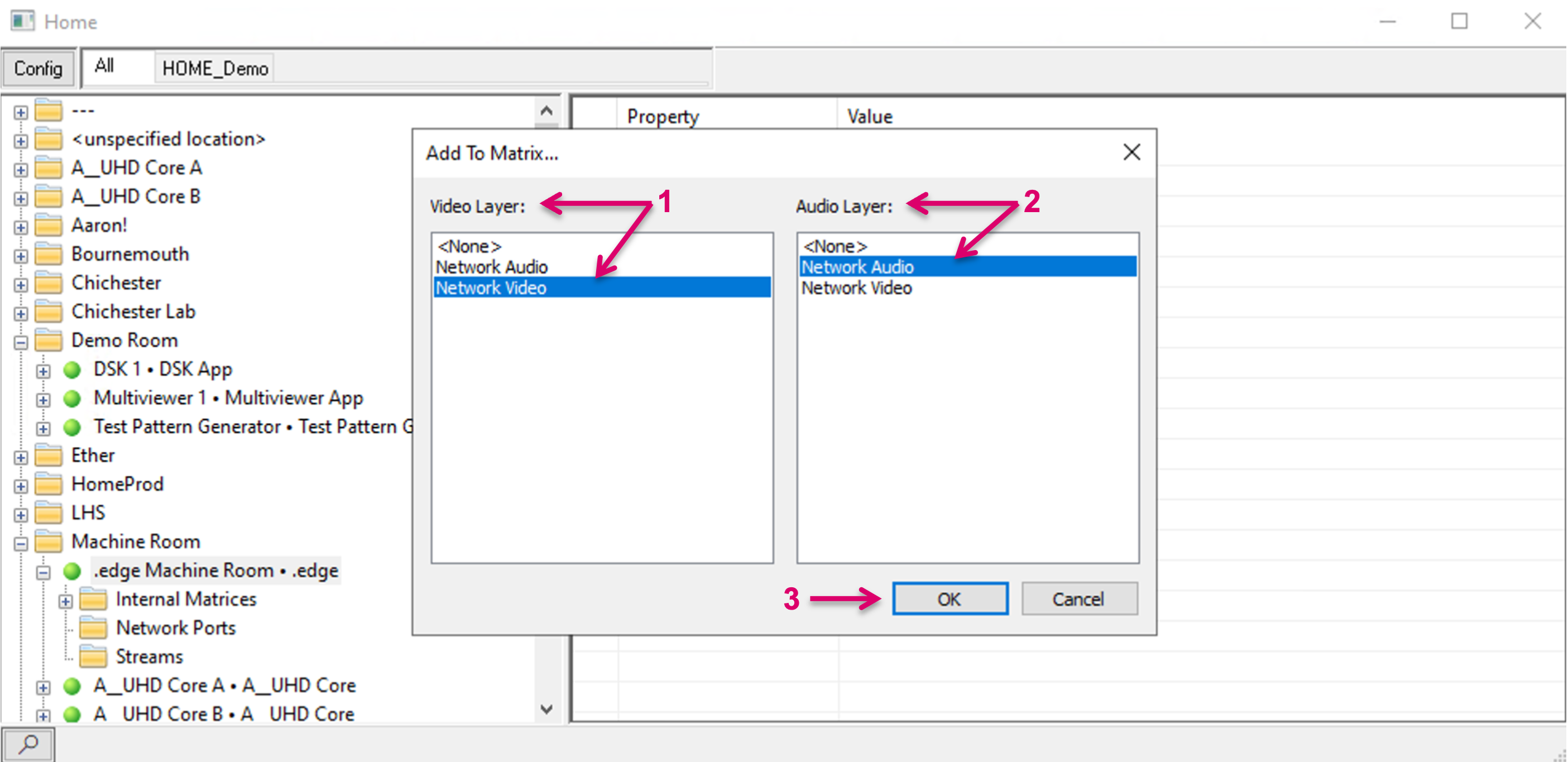
The number of available and free In- and Outputs on the respective Network Layers does not matter at this point, since the system will extend these layers by the number of the Signal paths that need to be created and will assign the new Signals accordingly. Signals Paths are available in Matrix view and Signal Paths list for further configuration.
Signal Paths are created with all necessary attributes. All settings are accessible as usual via Signal Path properties (1). Aside SDP relevant information (2), the HOME interface provides switch port specific information via LLDP, that is also automatically applied to the created Signal Paths (3). The created HOME Signal Paths are by default moveable (4), means if a HOME device moves to a different network interface or a HOME App is started on a different HOME Apps Server, even in an SDN environment, the system can handle all possibly needed re-routing, and no manual configuration or interaction is needed.
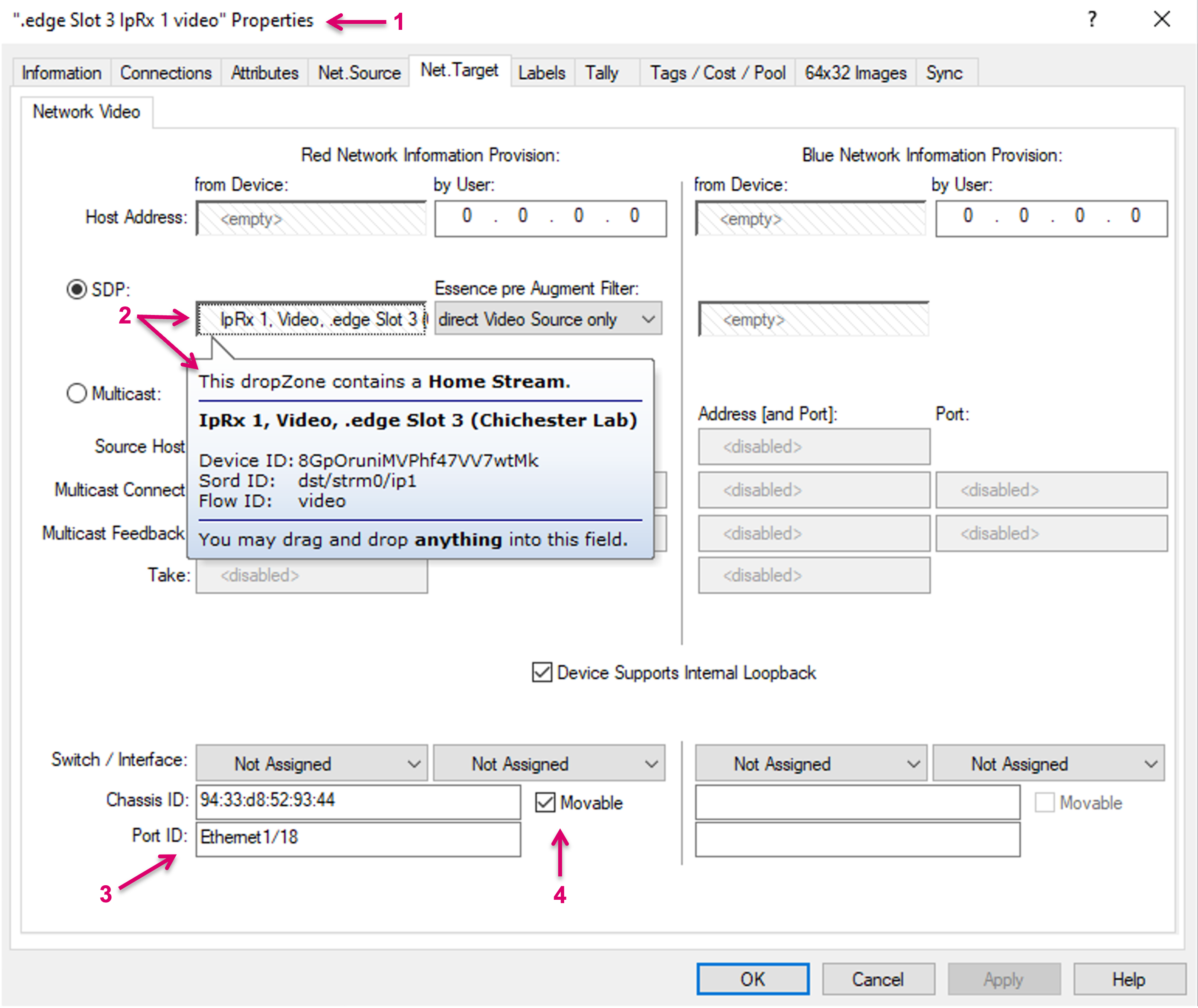
Switch port specific information via LLDP via HOME is only available for HOME native devices, including HOME Apps. This limitation is due to the fact that other devices, e.g., imported into HOME via NMOS importer, do not provide the respective data in the first place. In these cases, the Switch / Interface information must be configured manually.
HOME App MV specific
If creating HOME App MV resources via the system assisted configuration method, the system will not only create the Signal Paths but also map the related PIP Tally and Label Parameters accordingly.
System assisted Layer and Signal Path Creation for HOME resources
Specific for the HOME API interface and the, so called, HOME Internal Matrix resources, vsmStudio provides a system assisted configuration method. This method allows the system to create Layers, as well as the related Signal Path resources in a background process.
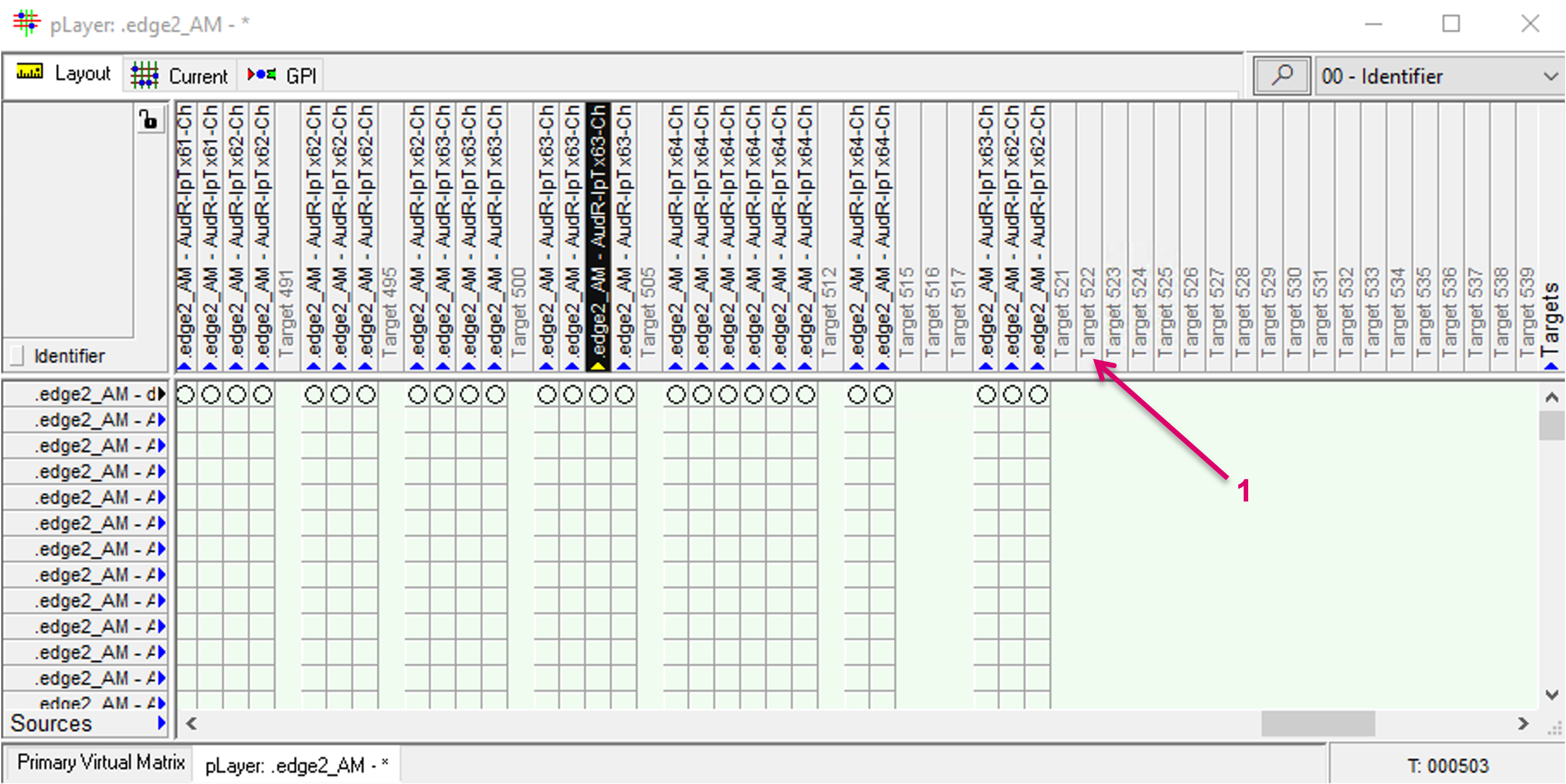
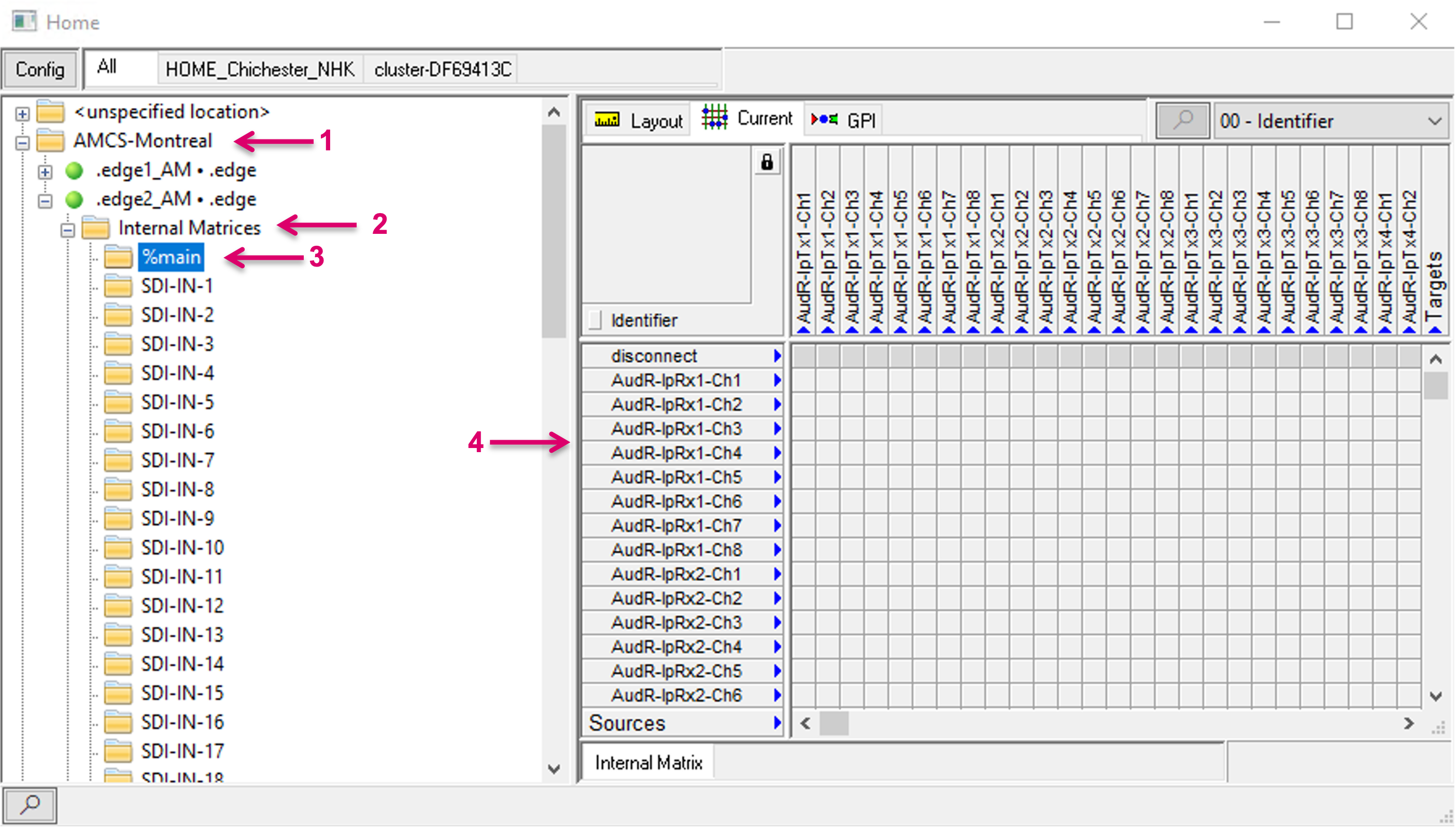
Where applicable, HOME Internal Matrices are exposed via the HOME API and will be listed per Location/HOME Device (1) in the HOME API view. To create a Layer representation including Signal Paths, open the top node of a HOME Device, navigate to Internal Matrices (2) and the respective Internal Matrix. Currently only Audio matrices are available and exposed, and the layer ID of the main Audio matrix is labeled “%main” (3). By selecting an Internal Matrix layer, all Source and Target resources of this layer are also shown in a Matrix overview in the right section of the view (4). These Sources and Targets only reflect the available device resources but do not provide full VSM Signal Path functionality. In this presented form, they cannot be used for any further configuration within the system, e.g., Panel button assignments.
Although it is possible to set xpoints on the physical device immediately, after selecting the “Current” tab, unlocking the Matrix view and clicking in there, there is currently no xpoint feedback in form of blue dots shown in this view.
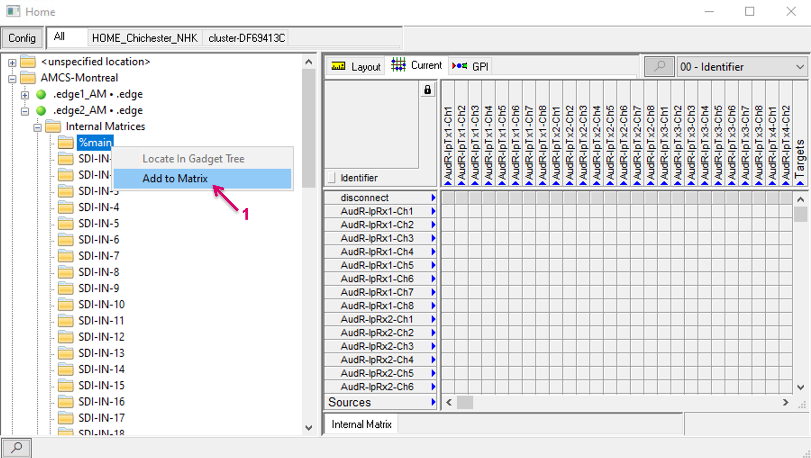
To create a Layer representation including all Signal paths in vsmStudio, right-click on the respective Matrix folder and select Add to Matrix (1).
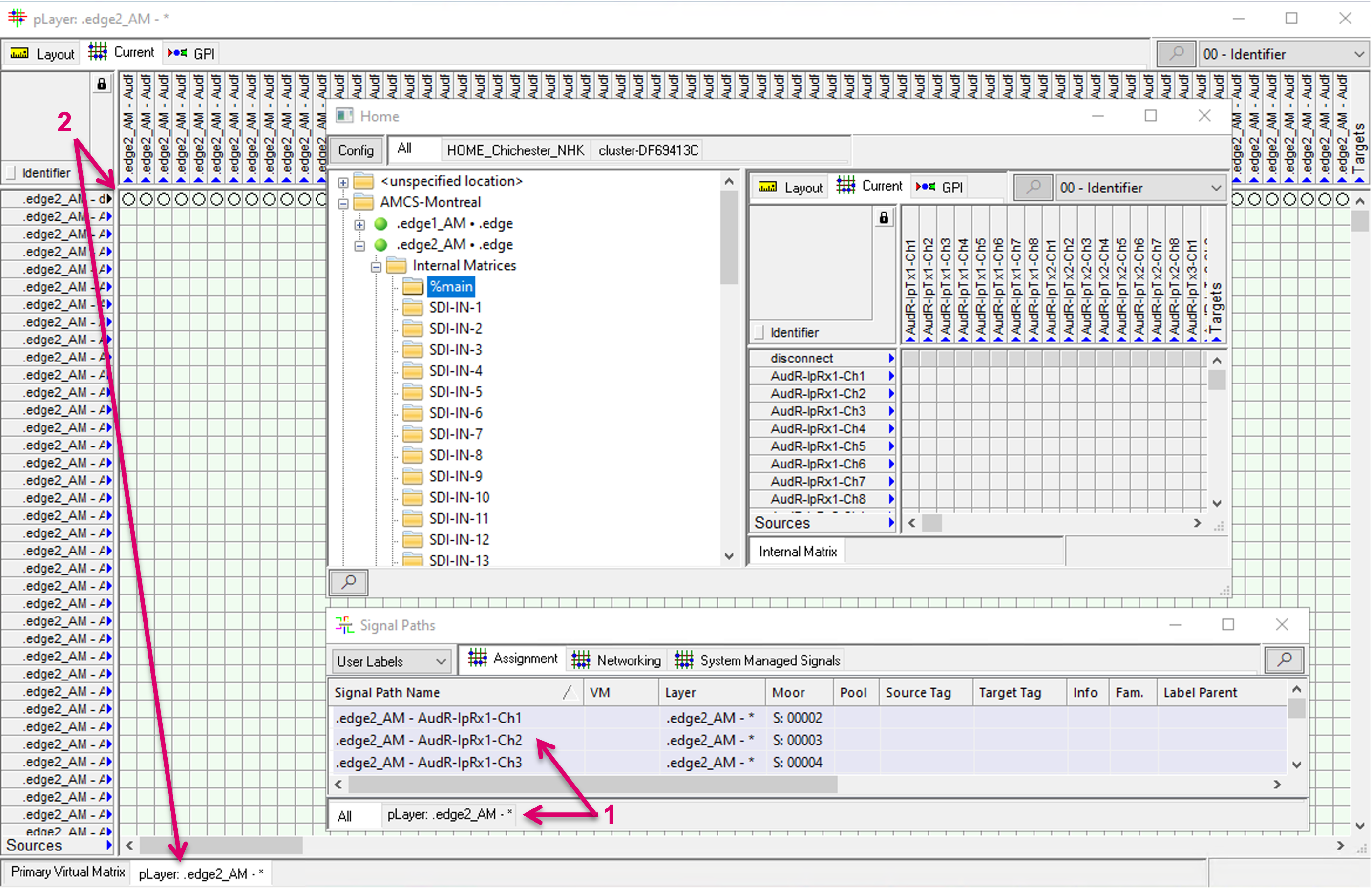
The system then creates the respective Layer, including Signalpaths, in a background process. The respective Layer, as well as related Signal Paths are displayed and accessible for any further usage in Signal Paths list (1) and Matrix view (2), etc.
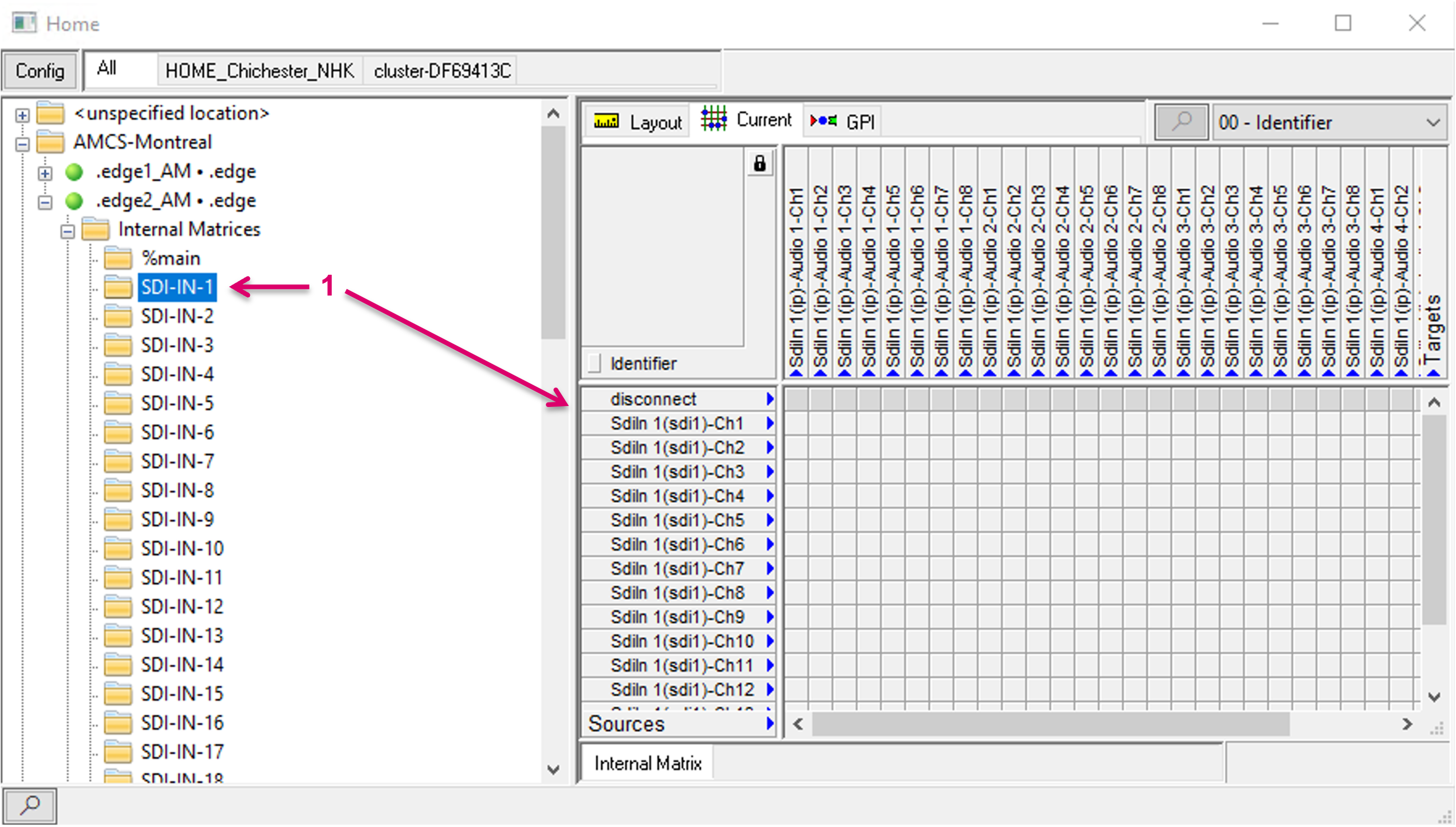
Some HOME devices may provide more matrices than one, e.g., .edge provides a separate Audio routing matrix for each SDI In and Out (1). The workflow to create these Layers follows the same process as described above.
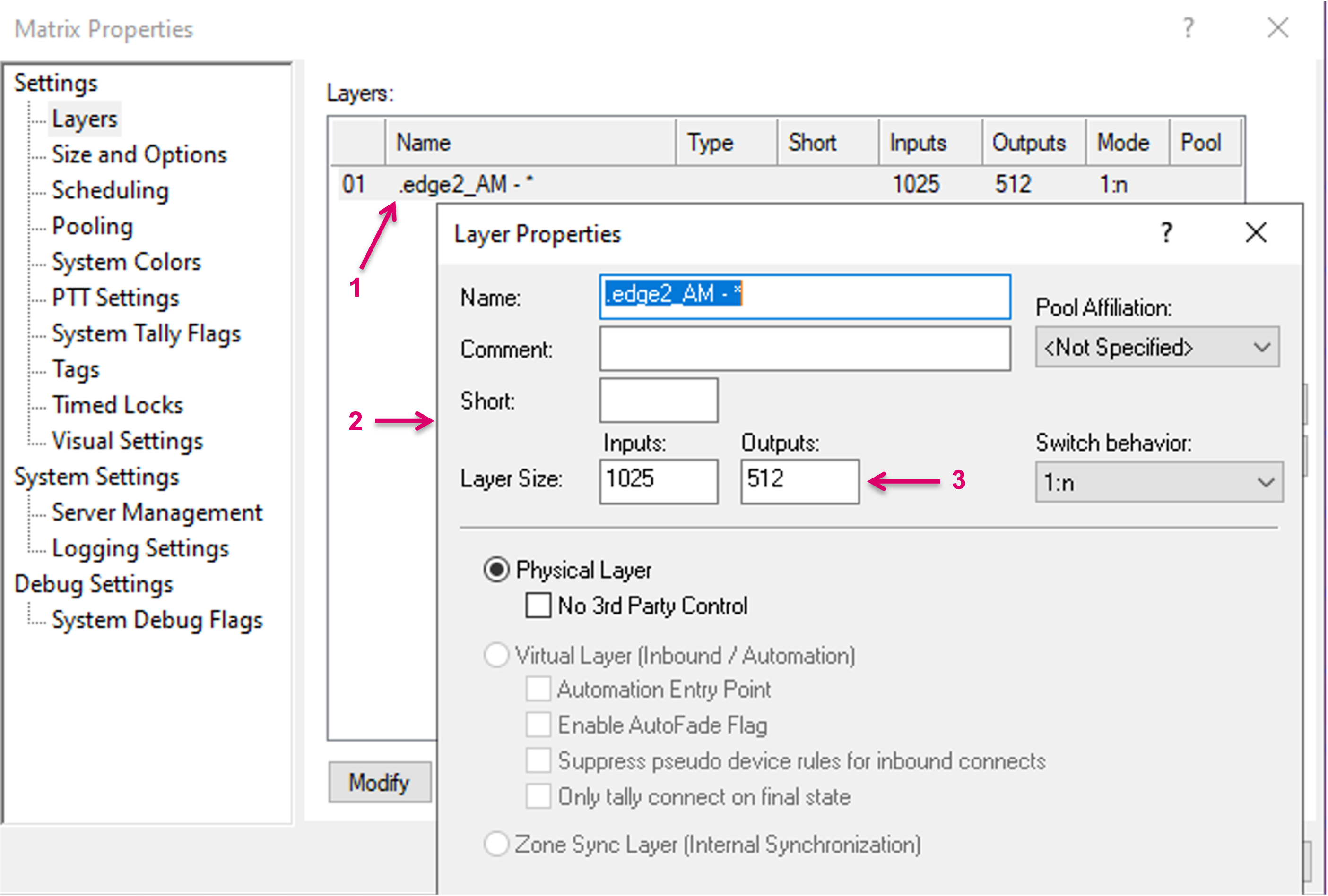
Properties of the system created Layers (1) can still be accessed and modified, if required, after creation (2). When created, the Layer size fits exactly the number of available Sources and Targets. But different to Signal Paths, that were assigned to manually created Layers with static defined protocol ID, the Signals on system-created Layers, have no association to a specific number on this Layer. This allows to move Signal Paths to different positions on the matrix, e.g., to sort them in different order or blocks for organizational reasons.
In order to move a Signal on the matrix, the respective target position must be free. Therefore, it will be required to manually increase the number of Inputs and/or Outputs accordingly (3).
Afterwards Signals can be moved, one by one or multiple at a time, to different (free) positions on the Matrix view (1).