diamond VX - First Steps
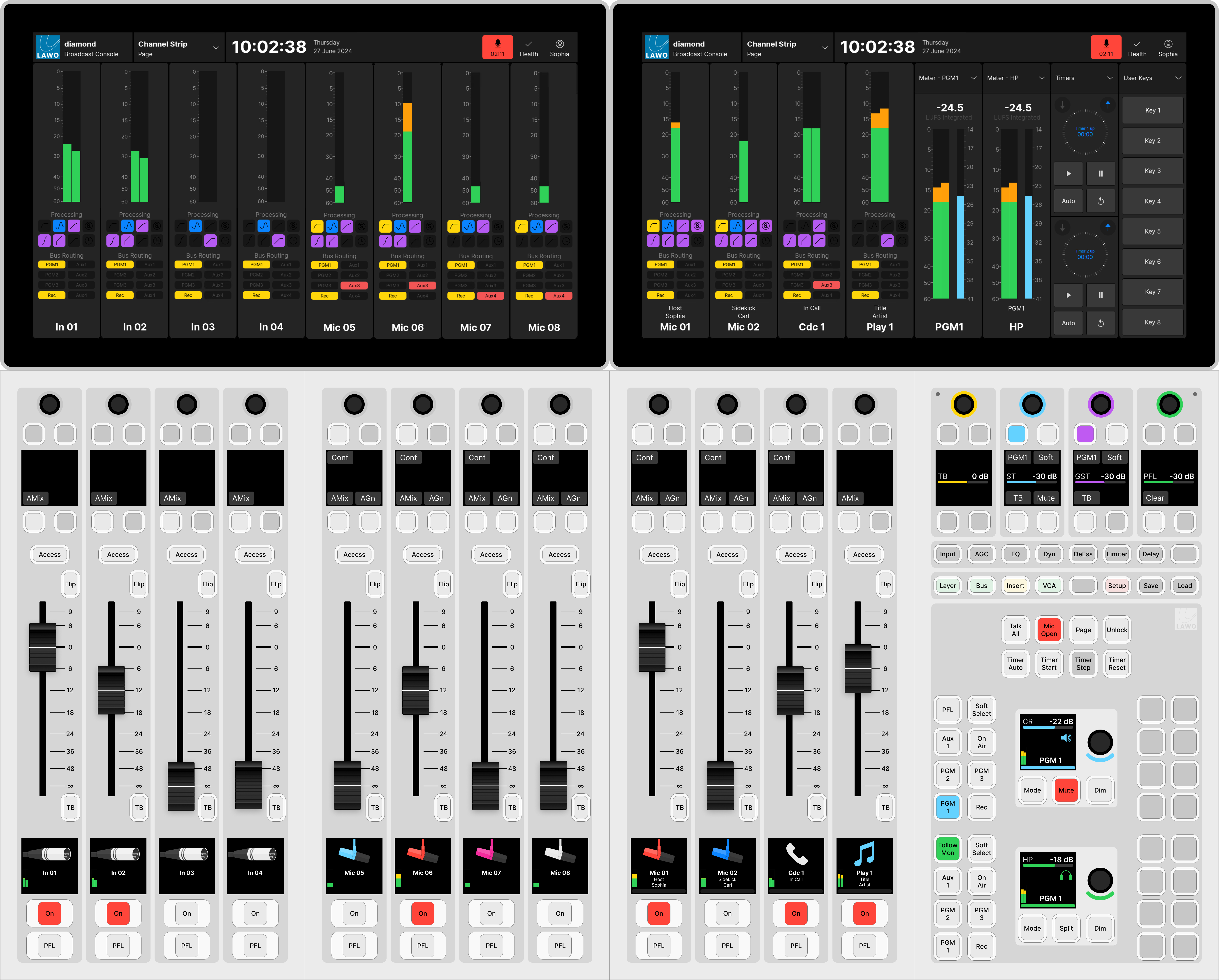
The Virtual Extension provides visual feedback and touch-screen operation. It can be integrated into the frame or delivered as a stand-alone unit. If the Virtual Extension is integrated, then the viewing angle can be adjusted by the operator (as described here).
The functionality of the GUI is defined by the configuration. This chapter describe the standard configuration (included with every console). The operation may vary if the configuration is customized.
Prerequisites
The VX software runs on a Windows 64-bit PC that must be supplied by the customer. A license to run the standard configuration is included with every console.
It is expected that the customer has prepared and connected the host PC. How to do this is described in diamond - Configuring the Virtual Extension.
If the surface has more than one VX module, then all of the displays should be connected to the host PC and powered.
Starting the Software
The VX runtime app is started by double-clicking on the start script icon. This starts the Main and Fader sessions (according to the initial settings defined in VX Admin).
In each case, the session loads and connects to the hardware. Providing there are no error messages, the VX display is ready for operation.
If the display does not look operational, then try the troubleshooting tips in diamond - Powering On.
Session Mapping
Once the sessions are running and connected to the hardware, check the configuration of the 'Channel Strip' page.

The number of channel strips and master slots should match the controls on the surface modules. For diamond, there are three possible layouts: a Fader session (with 8 channel strips) or a Main session (with either 6 channel strips plus 2 master slots OR 4 channel strips plus 4 master slots).
If there is a mismatch, check first the mapping of the Fader and Main sessions to the displays (using the "Screens" area in VX Admin). Then use the 'Settings → Surface' options (described below) to adjust the master slots.
Configuring the Main Session Slots
For the Main session, the number and position of the master slots can be adjusted as follows.
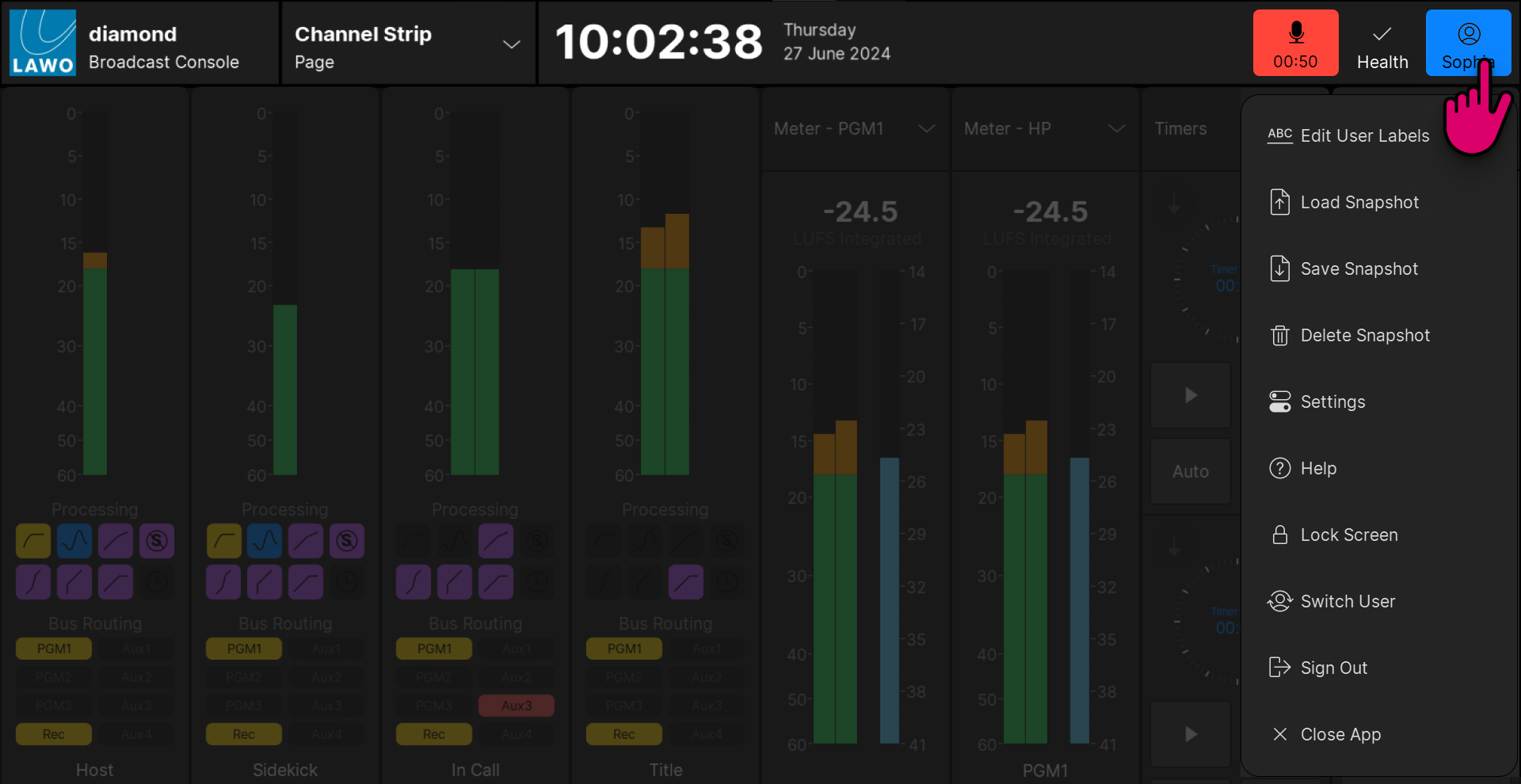
1. Touch the user name (e.g. Sophia) and select Settings (from the user menu).
You must be logged in to access the Settings button.

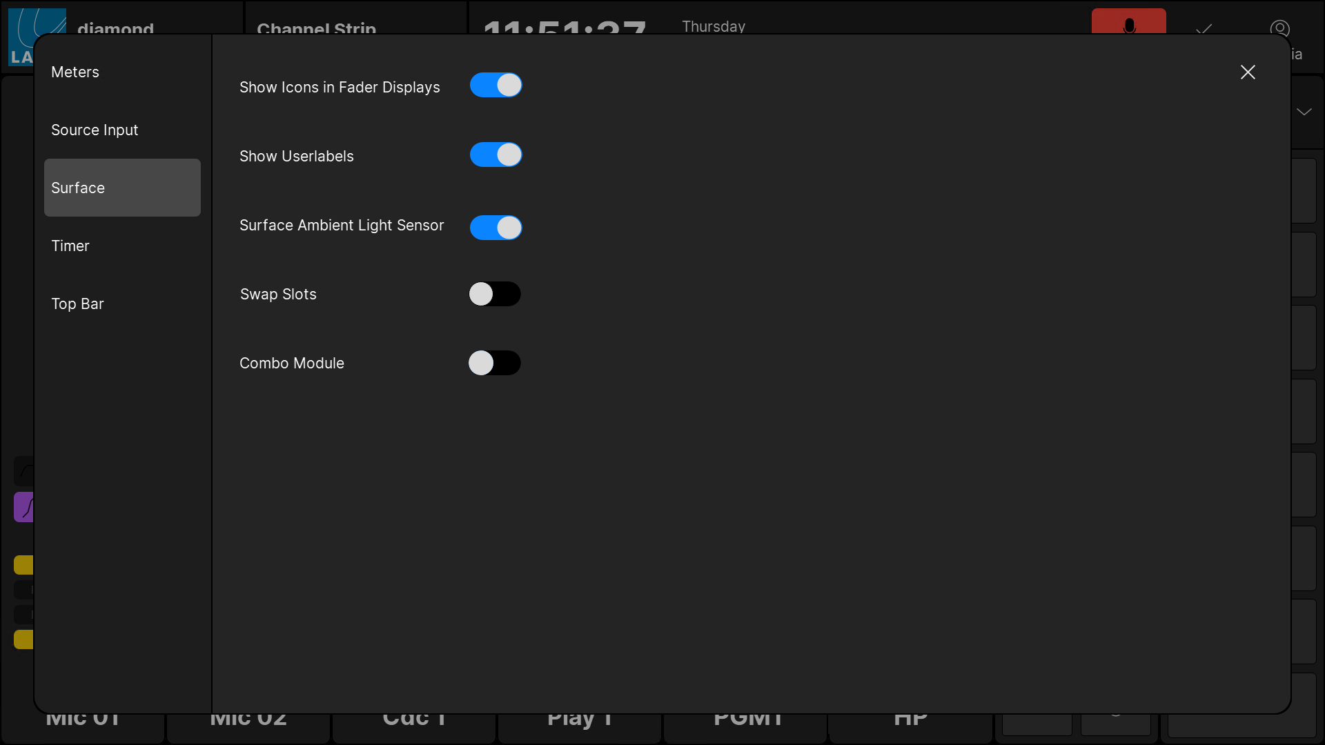
2. Select the Surface tab (to access the 'Settings → Surface' options).

3. Use the Swap Slots and Combo Module options as follows.
- Swap Slots - swaps the position of the channel strips from left to right. This option should be enabled if the Fader module is fitted to the right of the central controls.
- Combo Module - changes the layout from 4 channel strips + 4 master slots to 6 channel strips + 2 master slots. This option should be enabled if the surface is fitted with a Combo module instead of a Central module.
The images below show the correct settings for each possible layout.
Please note that any changes made from the "Settings" dialog box are not persistent, and are reset to the default values once the app restarts. Therefore, to make the changes permanent for all users, you should edit the Swap Slot positions and Combo Module options in the "Emberdefault.ini" file.