HOME - I/O Routing
The I/O Routing page is used to connect the IP channels of the senders and receivers to the physical audio I/Os of the device: Mic/Line, AES3, MADI, etc.
The operation is very similar to the "Signal List" display on Lawo's mc2 consoles. To make a connection, select a source (on the left) and a destination (on the right); then click Connect.
Opening the I/O Routing Page
Depending on how you want to view the information, there are three different ways to open the page.
- From the Senders tab, select a stream and click on I/O Routing. This method shows all of the device inputs (on the left) and the stream's IP channels (on the right).
- From the Receivers tab, select a receiver and click on I/O Routing. This method shows the receiver's IP channels (on the left) and all of the device outputs (on the right).
- Select the I/O Routing tab. This method shows all available sources and destinations.
The first two methods are ideal for making assignments to a selected stream or receiver. You can select more than one stream or receiver if you wish. The third method is best if you need a complete overview of the device. The images below show two examples.
")
")
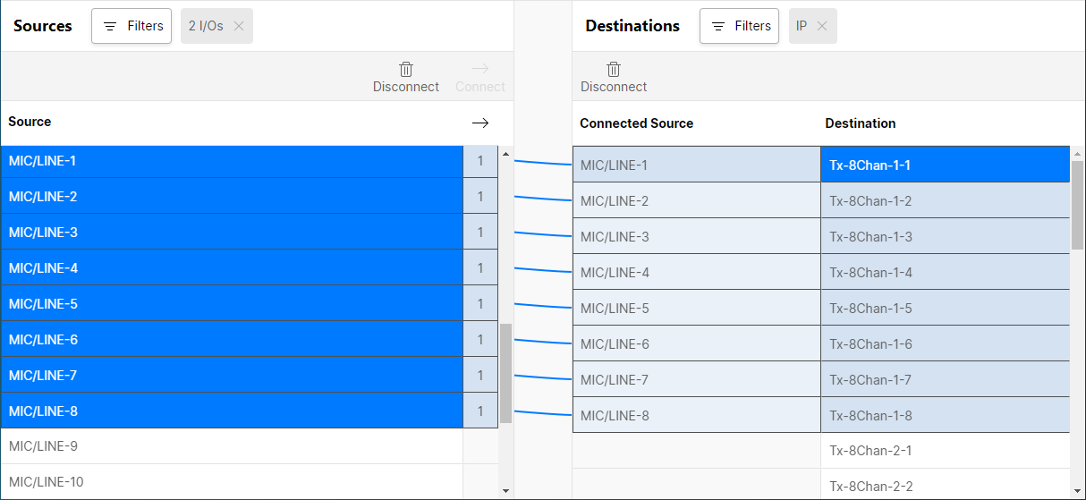
Once open, the page shows connections from "Sources" (on the left) to "Destinations" (on the right). Use the vertical scroll bars to scroll up and down each list.
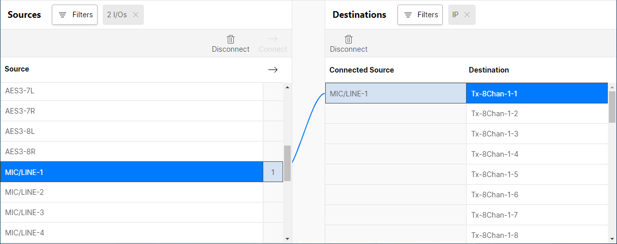
- If a destination is connected, then the source label appears in the "Connected Source" column. If the source is also in view, then a solid line appears.
- If a source is connected, then a number appears in the "source used" column. This indicates the number of connections made. i.e. the number of times a source is used.
Applying a Filter
To restrict the view, you can apply one or more filters. This is a good idea, especially if you have opened the I/O Routing tab and have all sources and destinations in view.
1. Start by selecting the "Sources" Filters button and choose Filter by type.
2. Select the sources you wish to view (e.g. AES3 and MIC/LINE).
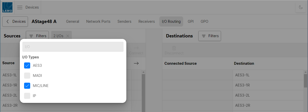
3. Click anywhere outside of the Filters box - the pop-up closes and the filters are applied.
4. Repeat to filter the "Destinations", but this time choose IP.
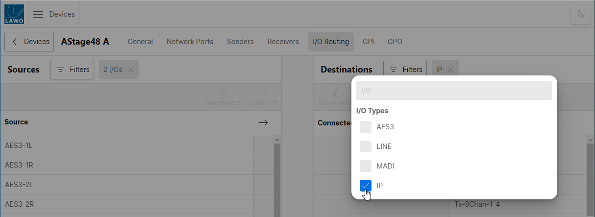
You should now see all of the AES3 and Mic/Line inputs (on the left) and IP channels (on the right). This view is ideal for connecting the device I/Os to the IP channels of the Tx streams.
Making (and Unmaking) Connections
The Connect and Disconnect buttons are used to make and unmake connections as follows.
Connecting a Source to a Destination
To make a connection, select a source and a destination.
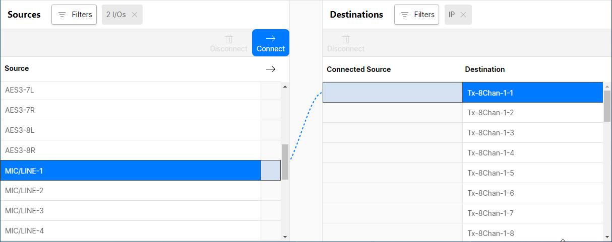
Then click Connect - the dotted (preview) line changes to a solid line and the "Connected Source" field updates.
Using Disconnect
To remove a connection, select either a source or destination and click Disconnect.
- If you disconnect a source, then all of its connections are removed and the "source used" field clears.
- If you disconnect a destination, then the connection is removed and the "Connected Source" field clears.
Connecting Multiple Sources to Multiple Destinations
You can select multiple sources and destinations by pressing and holding the SHIFT or CTRL buttons on your keyboard. This makes it easy to connect or disconnect multiple signals in one operation.
Follow the same steps as before, but press and hold SHIFT to select a range. Once a range is selected, press and hold SHIFT to increase (or decrease) the selected range. Alternatively, press and hold CTRL to select (or deselect) individual signals.
When you click Connect (or Disconnect), the assignments are made in one operation. For example, to connect eight sources to eight destinations.
If there is a mismatch between the number of selected sources and destinations, then the routes are made on a best-effort basis as follows.
- If there are eight sources and only four destinations, then the first four sources are assigned consecutively to the first four destinations.
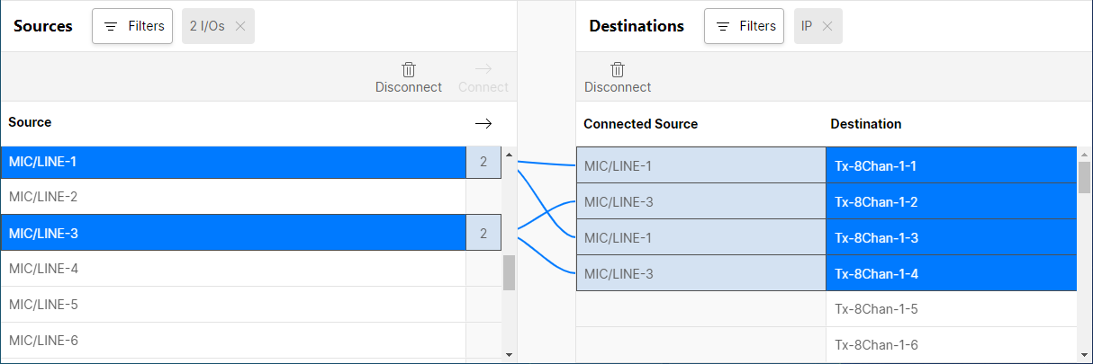
- If there are two sources and eight destinations, then the sources are repeated to each pair of destinations (as shown below).
Reversing the Filters
Remember to reverse the filters to connect the receiver's IP channels to the device's physical outputs.