vsmStudio - vsmShare

Introduction
vsmShare allows to share Signal Path resources between separate vsmStudio clusters and system topologies. Along the Signal Path shares, the system will share Labels, Tag and Pseudo Device Information as well as Lock states for Targets. Sharing Source Tally information from Consumer to Provider can be enabled and configured optional.
While we distinguish between a share Provider and a share Consumer, each system can be both at the same time. The vsmShare feature must be enabled via the vsmStudio license key on all Servers of a Cluster that acts as vsmShare Provider.
By design, the operational sharing workflow is that on Provider side an operator can choose from a Panel UI which Signal paths he wants to share with a remote system. On the Consumer side, an operator gets access to these resources and can use these in his local workflow. The underlying pathfinding and exchange of relevant information is handled in background processes on the connected systems.
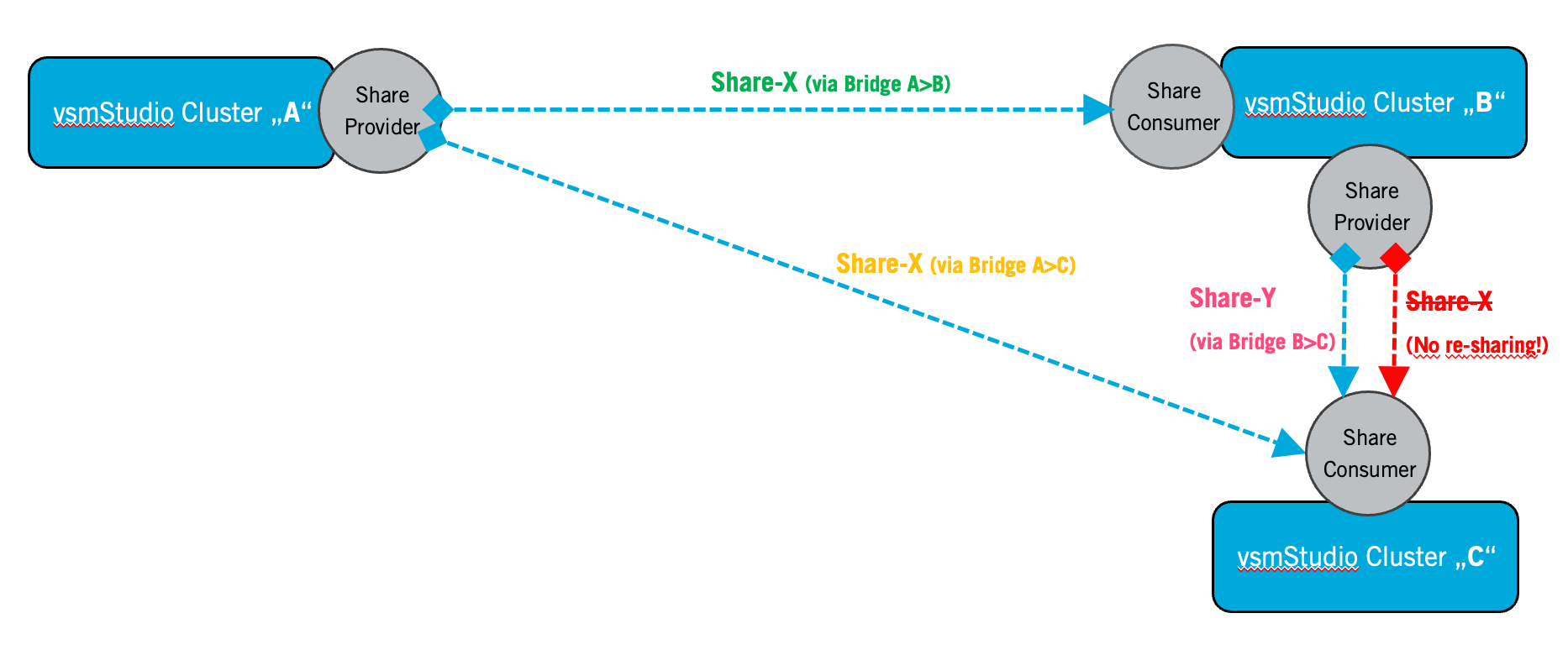
One Provider can share the same resource to multiple Consumers (via dedicated, separate Bridges). Distinct and different resource sharing to various Remote Locations may come available in a future release. Re-sharing a received Share is not supported.
Preconditions
A couple of preconditions and configuration alignment of the connected systems apply.
- Connecting systems via vsmShare, that run the same configuration file basis, or in other words, copying a configuration file from one system to another and then using the vsmShare feature between these systems, is currently not supported. Unique signal identifiers are stored in the configuration and therefore will lead to conflicts and malfunction, whenever such systems, sharing the same configuration basis, are connected and “see each other”.
- The vsmStudio software version on the connected systems should be ideally the same. While compatibility between different versions is clearly intended, optimization or modification work on this specific feature still bear the risk of leading to incompatibilities or unexpected behavior if running on different versions.
- The bandwidth settings of Layer and Signal paths on the connected systems shall be the same. If sharing a signal, the Providing system will send information about the shared resource to the Consumer which includes Bandwidth information. This information is crucial in an SDN environment. If the same Provider Bandwidth setting is not available on the Consumer, the system will still try to execute the route and may choose the next appropriate bandwidth available on the Consumer side. This may result in unexpected or blocking behavior due to wrong bandwidth reservations on the SDN layer.
- The general network layer configuration approach on the connected systems shall be the same. E.g. One layer for Video+Metadata, one layer for Audio.
- In order to properly resolve Pseudo Device logic, the respective Pseudo Device layer/columns which shall be included in the resource sharing process, must be named identical on Provider and Consumer side. Avoid duplicate naming of columns.
- Re-sharing of resources (multi-hop) is not supported and must be avoided by appropriate care in the workflow configuration. Re-sharing may cause the vsmShare feature not working anymore. The possibility to re-share may be disabled in later versions.
- Each Provider >Consumer connection must use separate, dedicated Bridges. Sole exception to this principle may be made in case of the exclusive use of "preassigned Bridges".
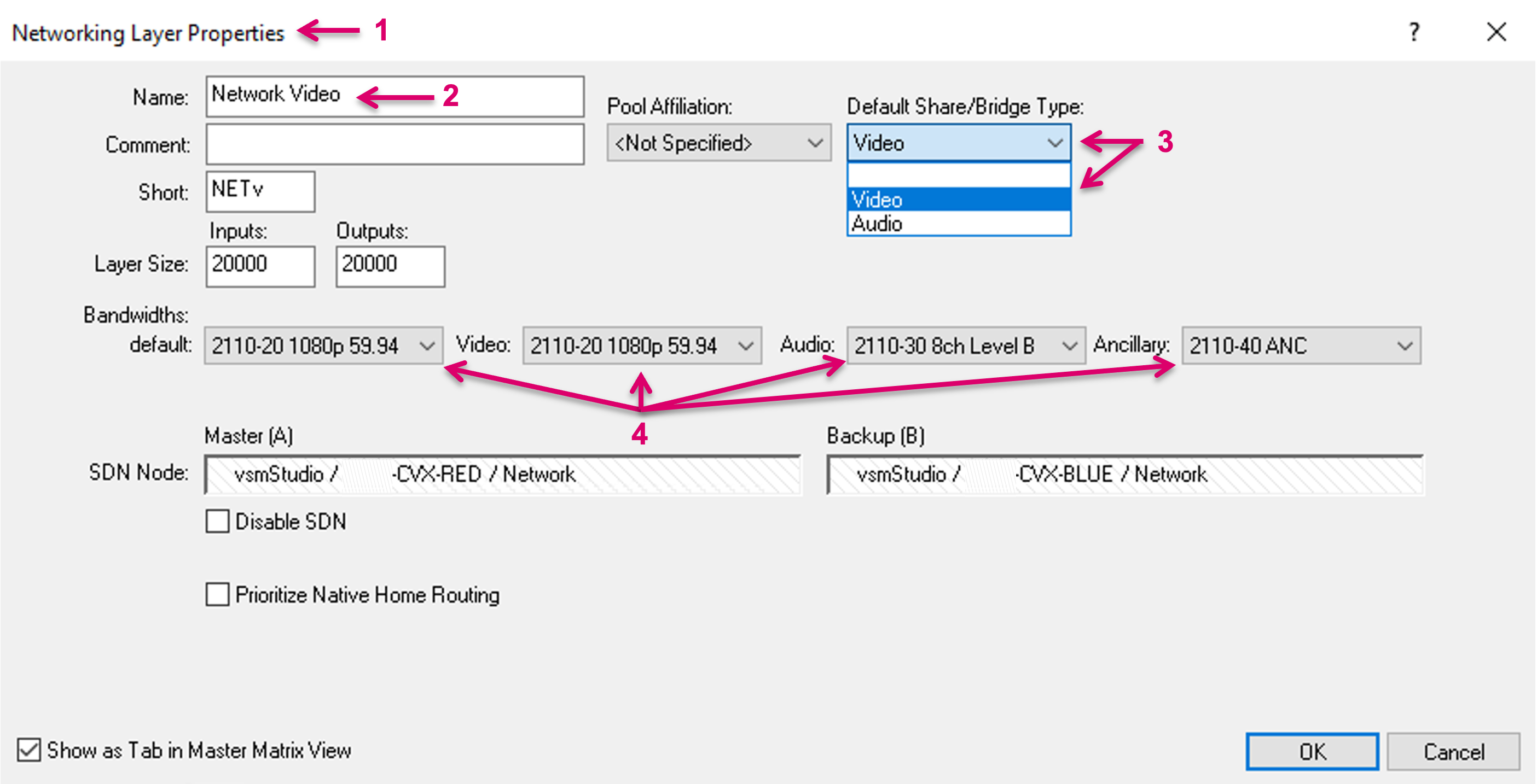
Layer setting example below. In the Networking Layer Properties (1), for the respective Network layer application (2), set the "Default Share/Bridge Type:" accordingly (3). Make sure the Bandwidth settings are correct and the same on the connected systems (4).
vsmShare Provider
Connect or remove connection to a Remote Server
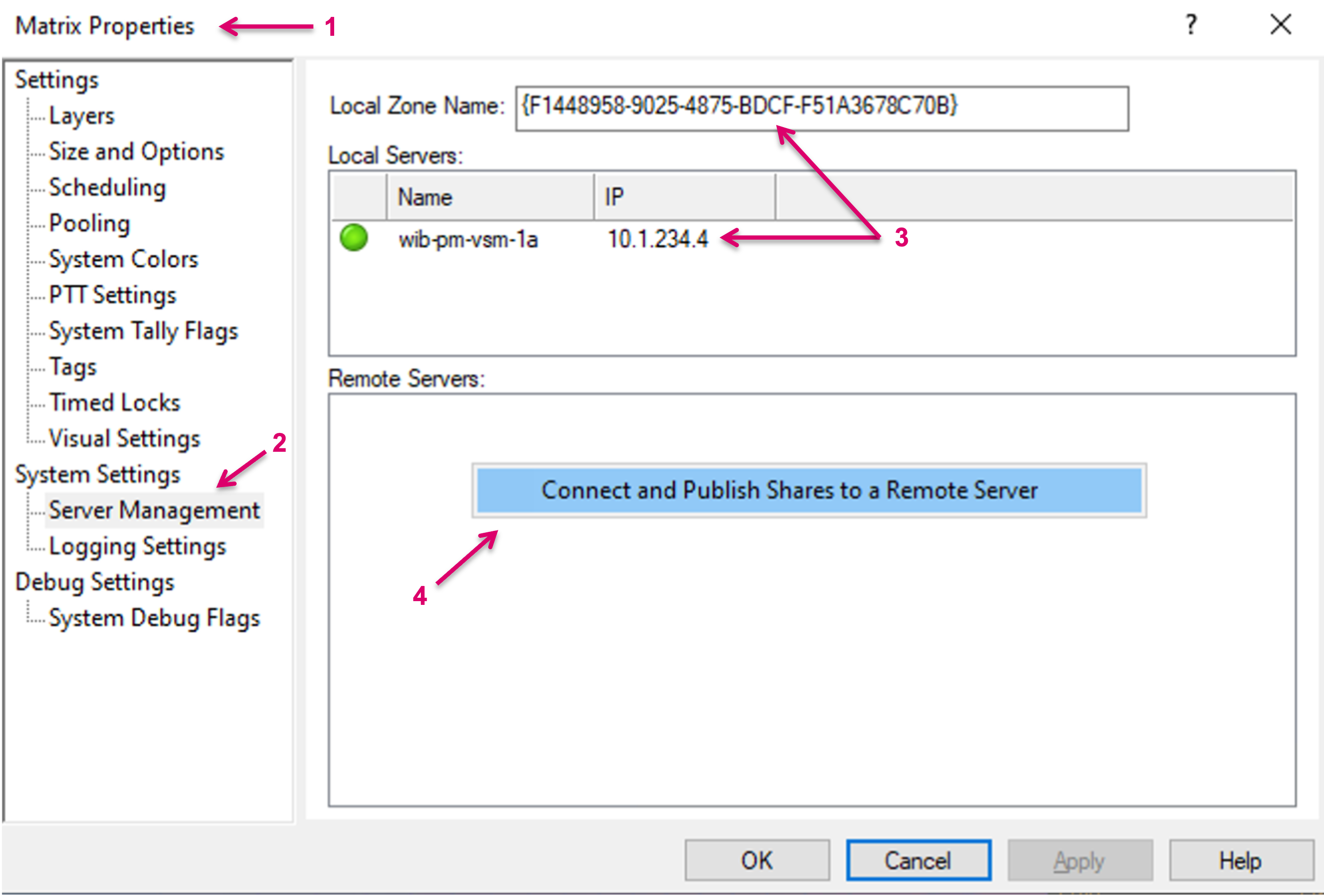
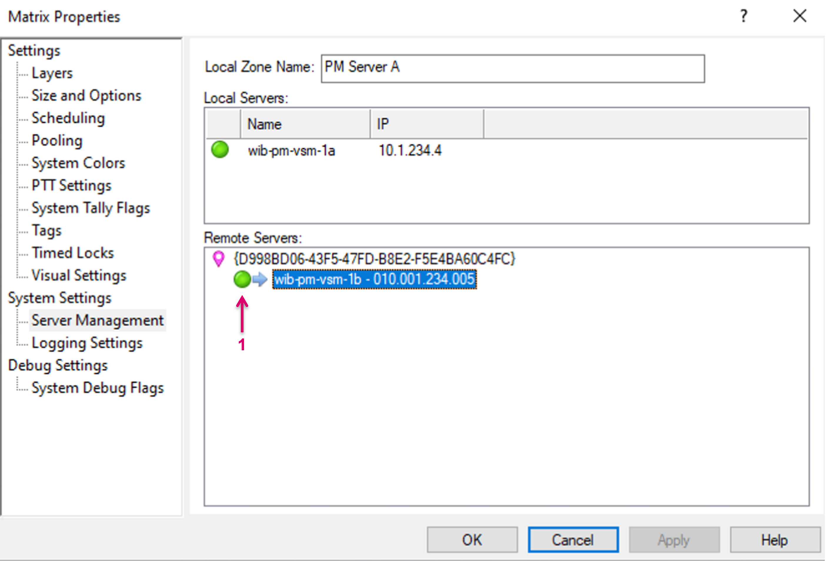
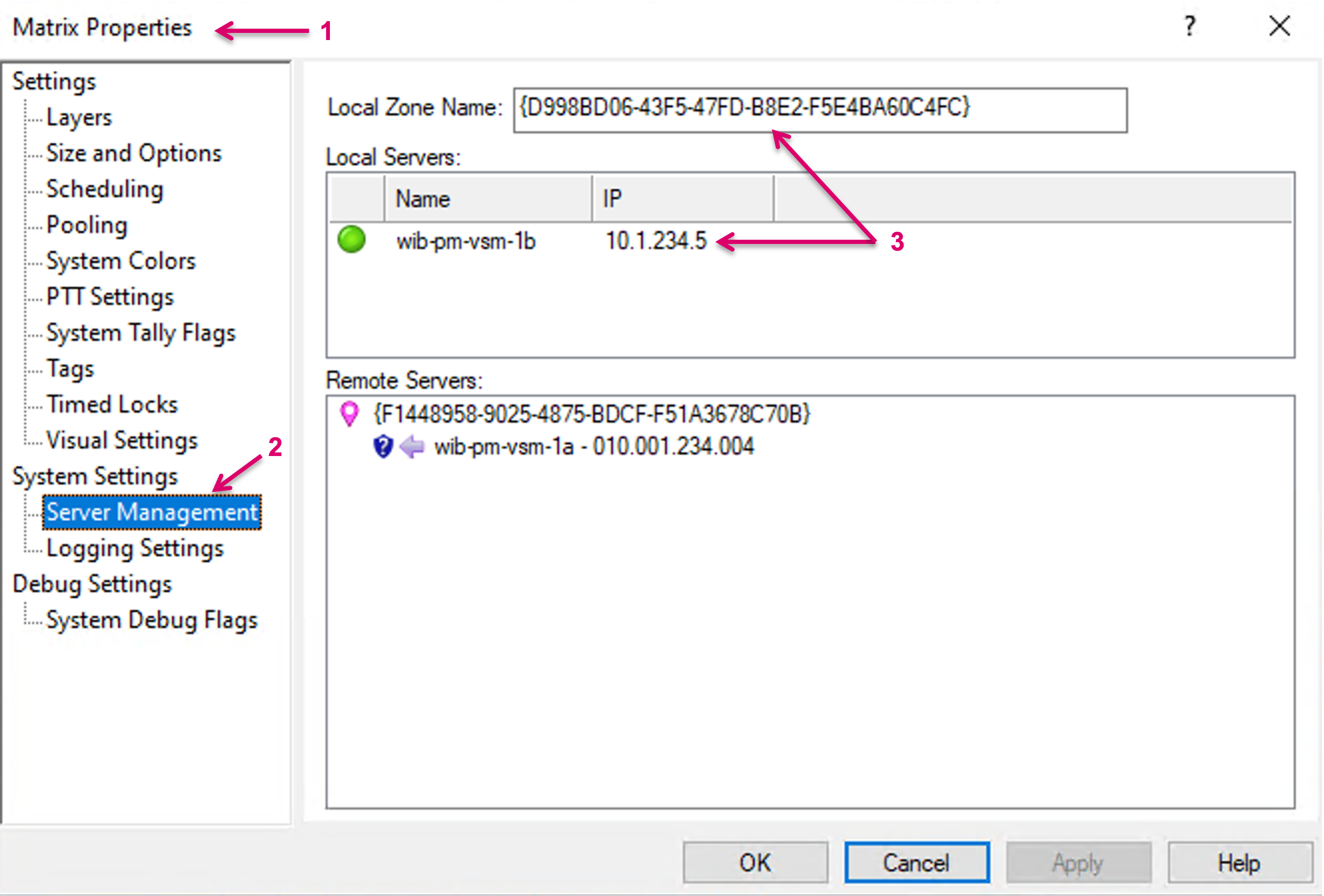
To share signal resources, first a connection to a Remote Server must be set up. Remote Server connections are administrated in System/Matrix Properties (1). Click System Properties and navigate to System Settings and Server Management (2) via the left-hand menu column. The local cluster Servers are listed under Local Servers and the Local Zone Name is displayed on top (3). Right click into the field Remote Servers and select “Connect and Publish Shares to a Remote Server” (4).
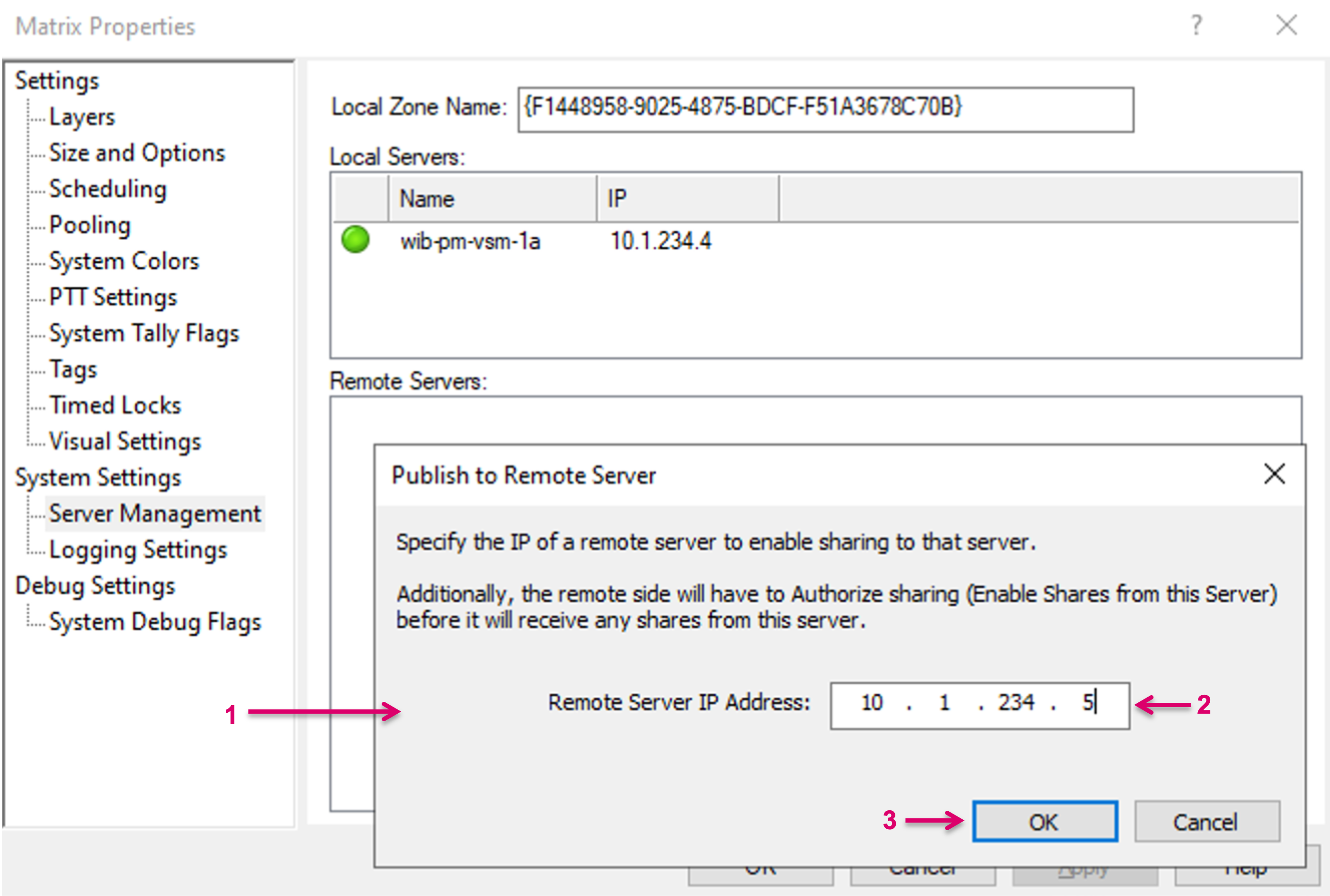
A pop-up window opens (1), where the Remote Server IP address can be entered (2). Confirm with OK (3). Repeat the steps for any further Remote Server connection.
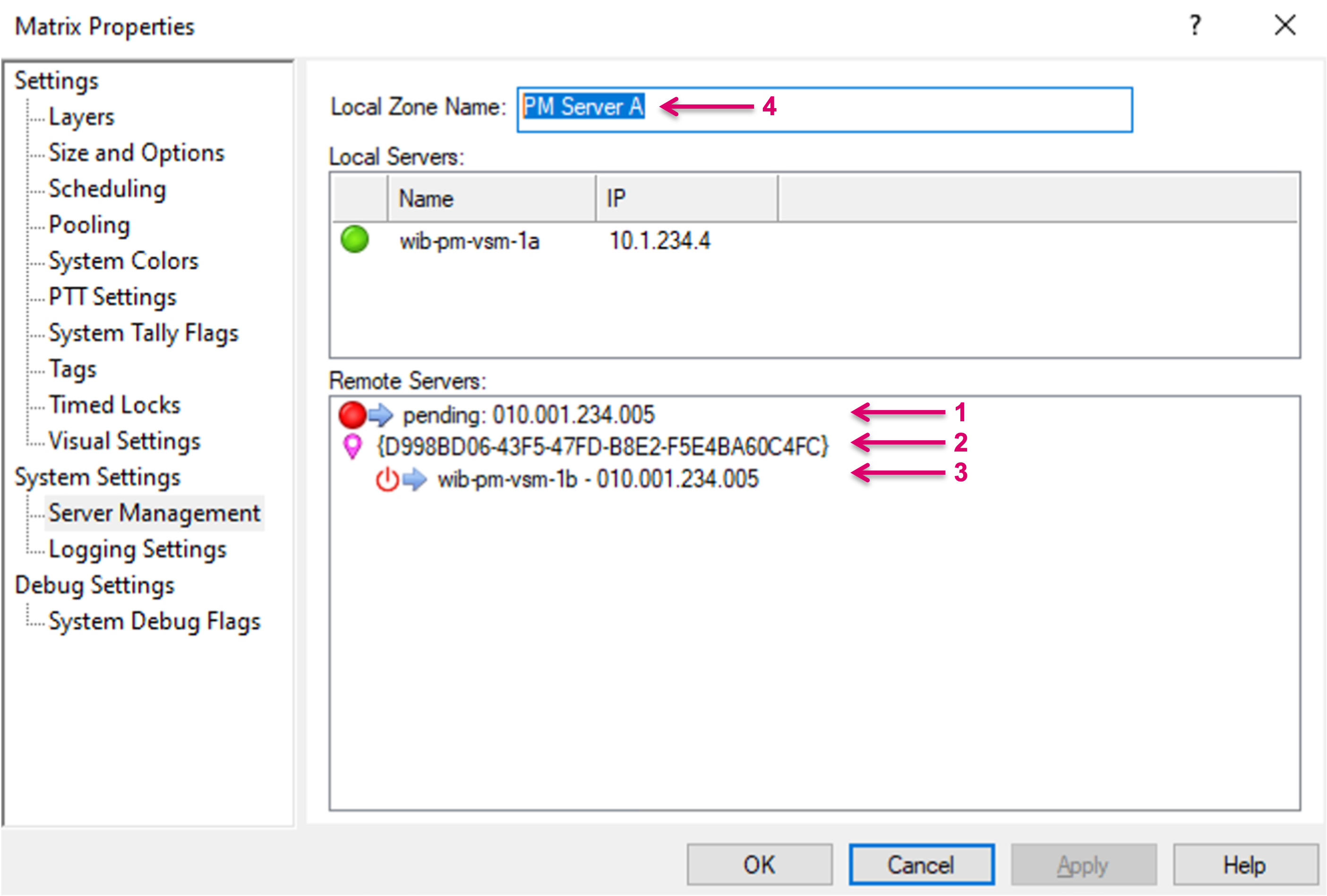
A connection shows pending (1) until the Remote Server (Consumer) has confirmed the incoming connection. The Local Zone Name of the Remote Server is displayed (2), as well as the IP address and Server Name (3). The Local Zone Name, initially displayed as numeric string, can be modified and replaced by a more descriptive name (4). The Local Zone Name will also be displayed on the Remote Server(s).
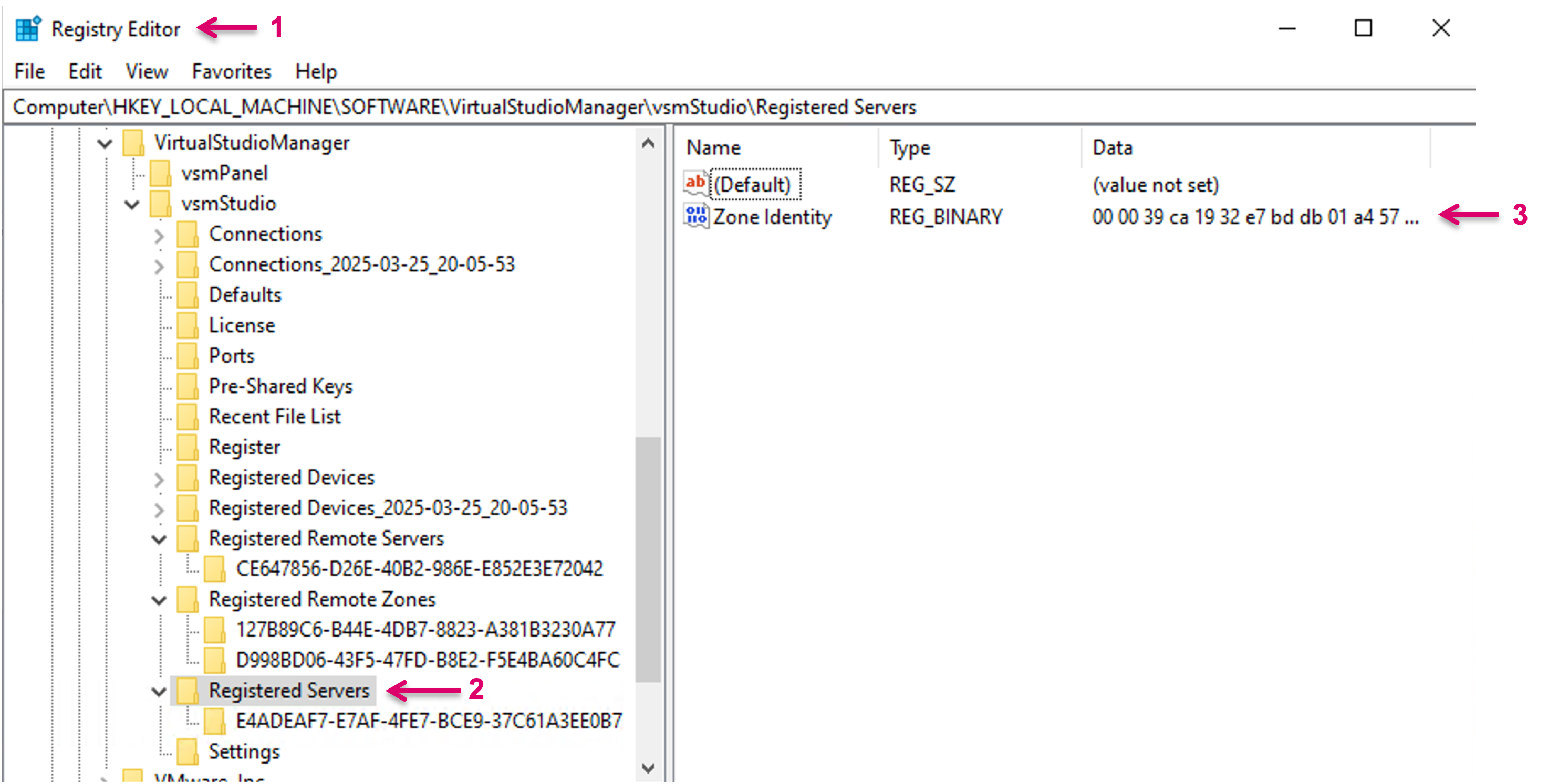
While the Local Zone Name will be displayed as indicator, this is just an alias for an underlying System related Zone ID. While the alias is stored within the configuration file, the System Zone ID is stored in the registry of the local system.
To disconnect a remote server, select the respective connection and select “Revoke Sharing and Remove Connection to this Server” (1). This action is followed by a confirmation dialogue. While the entry will be deleted from the list, right after confirmation, the selected Server may be first deactivated on the next vsmStudio restart.
The status indicator will show green once the connection to the remote Server is established (1).
The Remote Server configuration is stored, including Zone ID, with a timestamp, locally on each Server of the cluster. If replacing or adding a Server in the Cluster, where the respective new Server had vsmShares configured before AND comes with an OLDER Zone Identity-timestamp, the respective Zone ID of this Replacement-Server will be used and overwrite the Zone ID of the whole system. This may affect the system in a way that all configured vsmShares won’t function anymore. Saving the current Zone ID should always be part of any manual backup process. To prevent the risk of an older Zone ID entering an existing system when adding a new Server, no Zone ID should be stored in the new Server at time of joining the cluster.
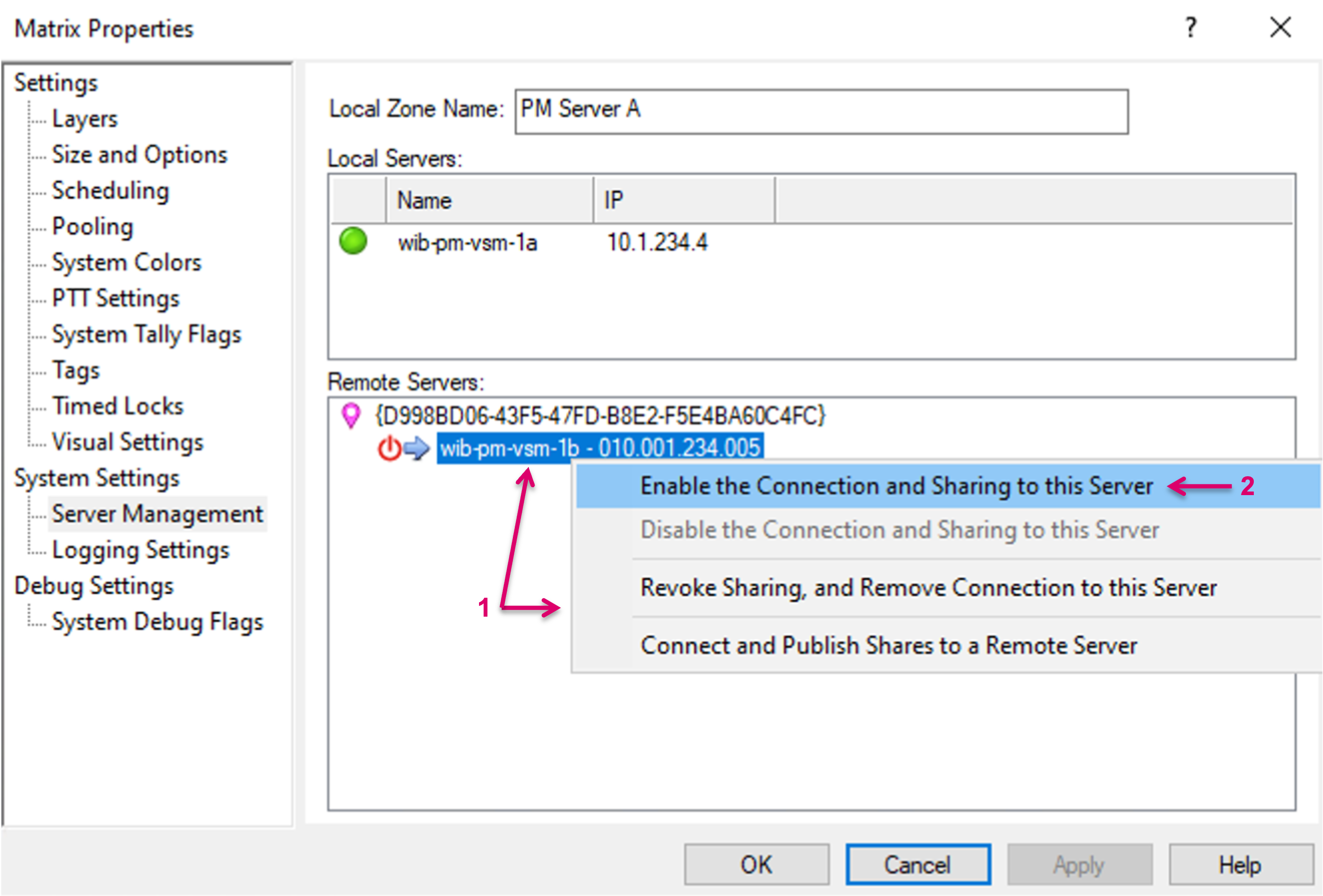
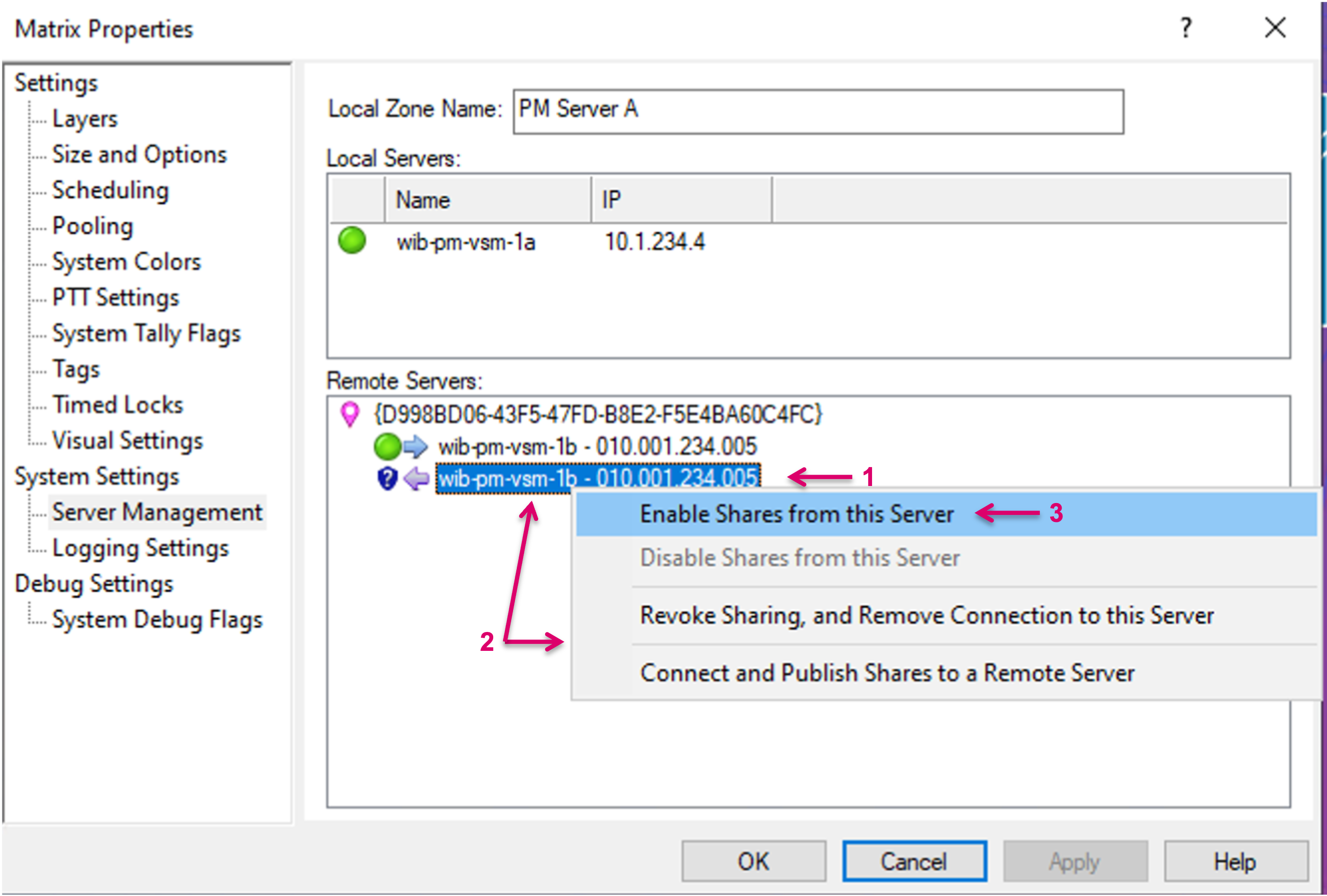
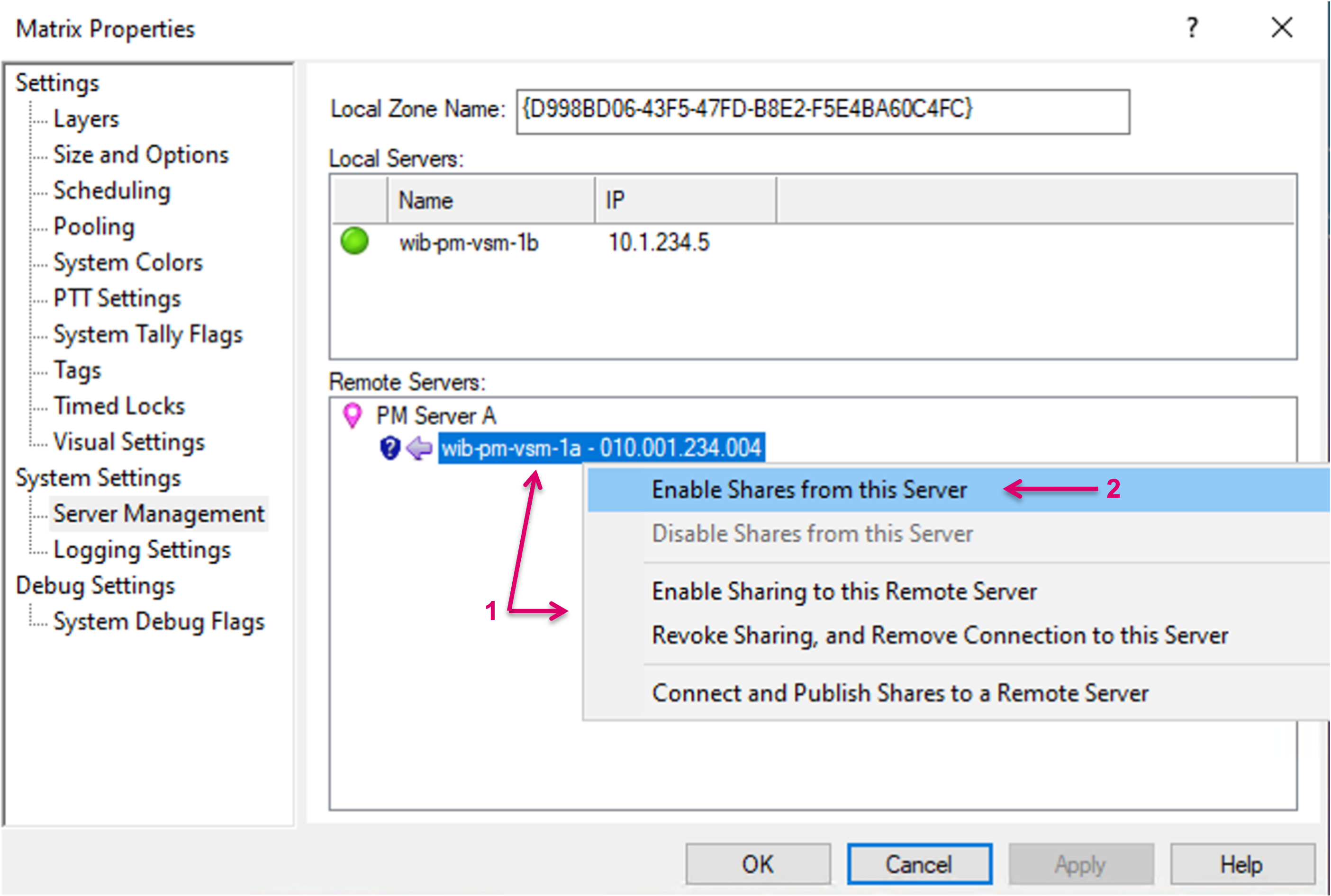
While each system can be both, Provider and Consumer at the same time, the Remote Servers area will show a second entry for a Remote Server (1) if this Server intends to share resources as well (see Consumer section). Before resources can be consumed, a confirmation is required. To do so, right-mouse-click on the respective entry (2) and select “Enable Shares from this Server” (3) from the pop-up dialogue.
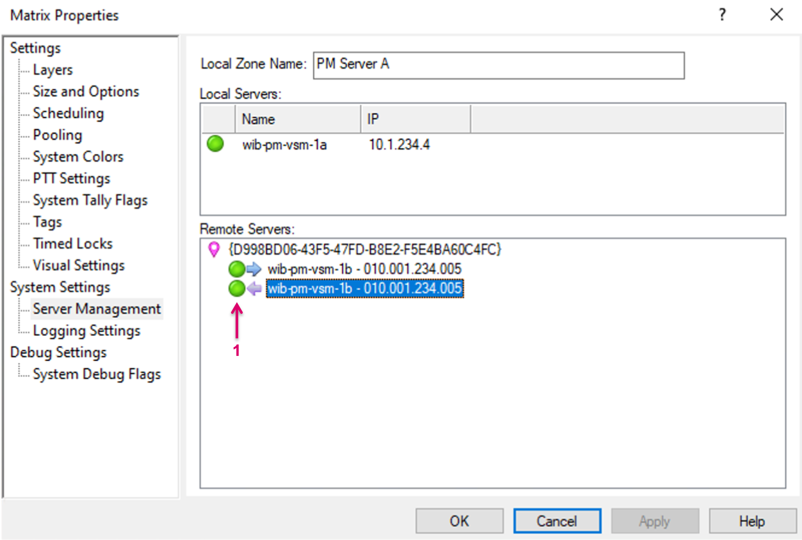
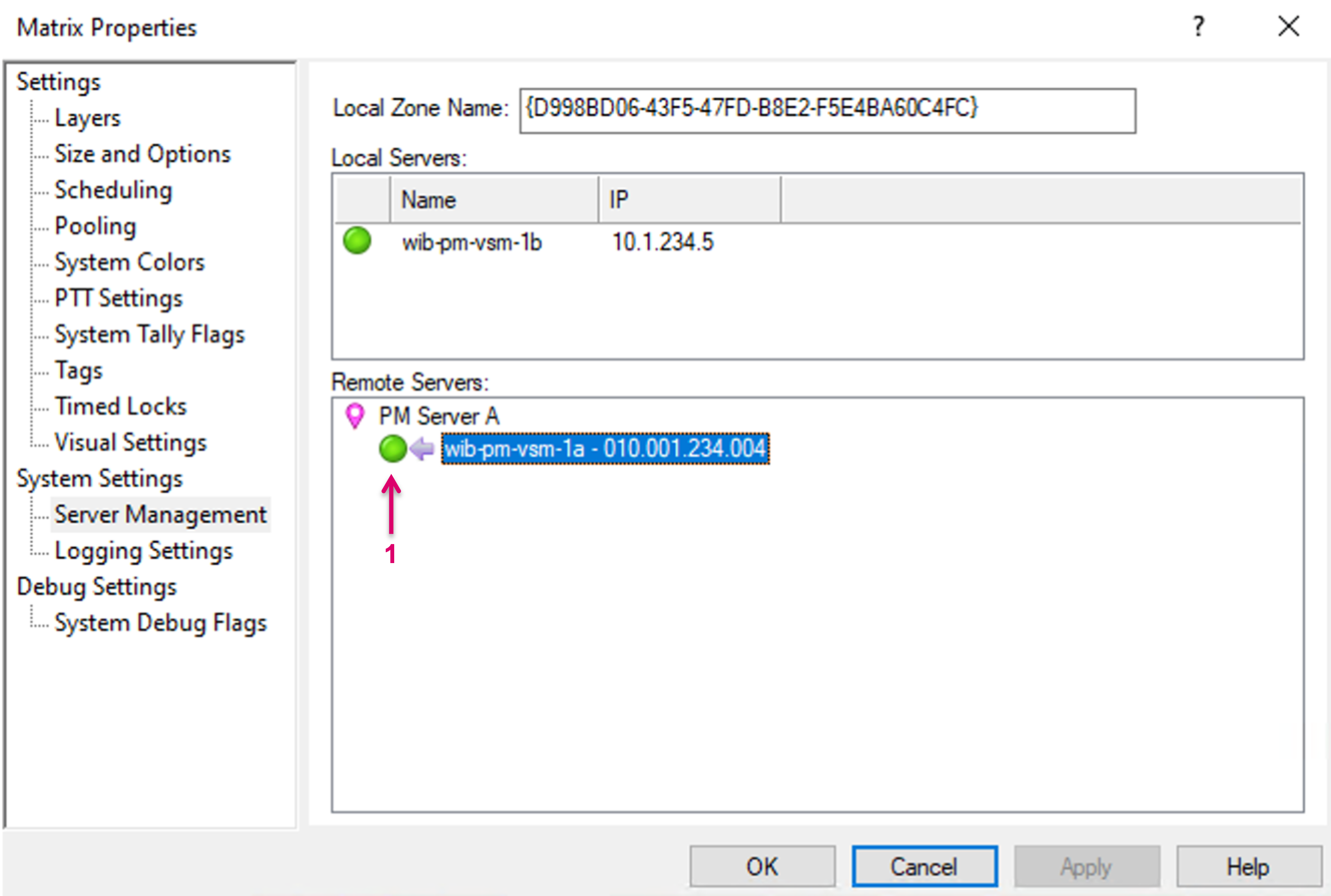
The status indicator will show green once the connection to the remote Server is established (1).
Create Signal Path Bridges
Before local Source or Target Signal Paths can be shared, it is mandatory to create “Bridges”, which represent the network Tie-lines between the connected systems. There is no differentiation between Bridges for vsmShare Sources or vsmShare Targets.
Bridges must be created on both, Provider (as Target) as well as Consumer (as Source) System separately but with the same Bridge Identifier, as explained in more detail below.
The number of available Bridges defines the possible number of parallel Signal shares. Please note that the system does not differentiate signal formats, so the number of bridges must be calculated based on the maximum available link bandwidth, divided by the maximum bandwidth expected of any signal that is going to be shared. In a system with one single house-format this is easy, in case of a mixed format infrastructure, you will need to calculate with the higher bandwidth to avoid oversubscription on the network links.
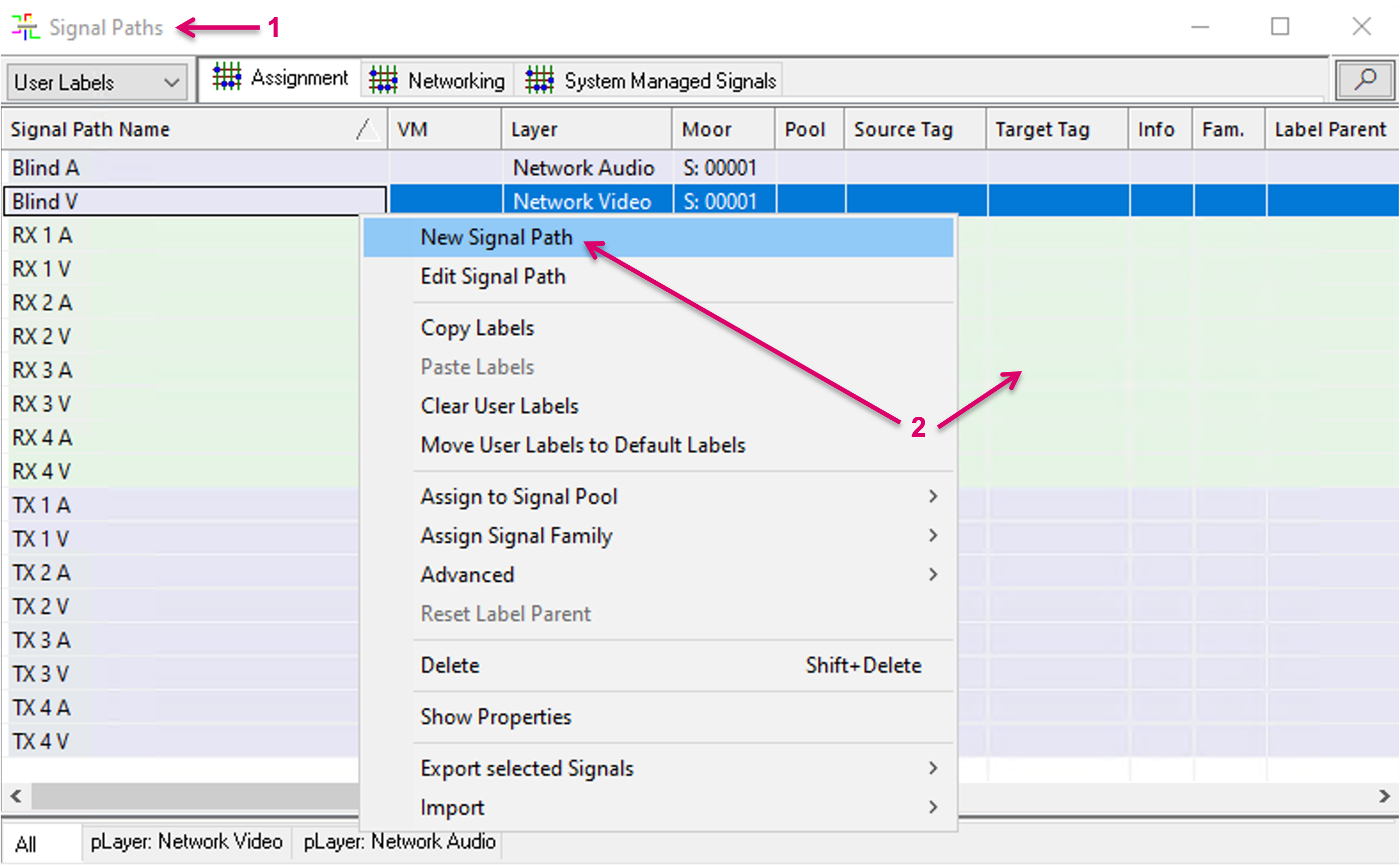
To create a Bridge, open the Signal Paths list (1). Right click into the window and select “New Signal Path” (2).
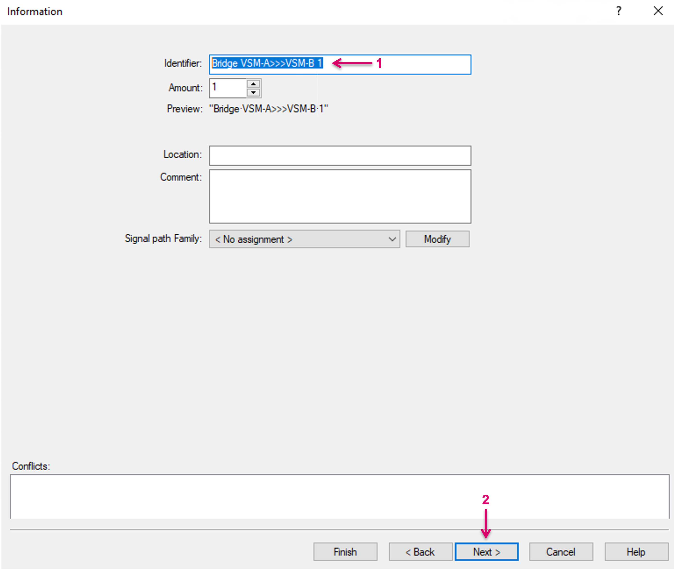
Assign an Identifier name (1) and proceed with “Next” (2).
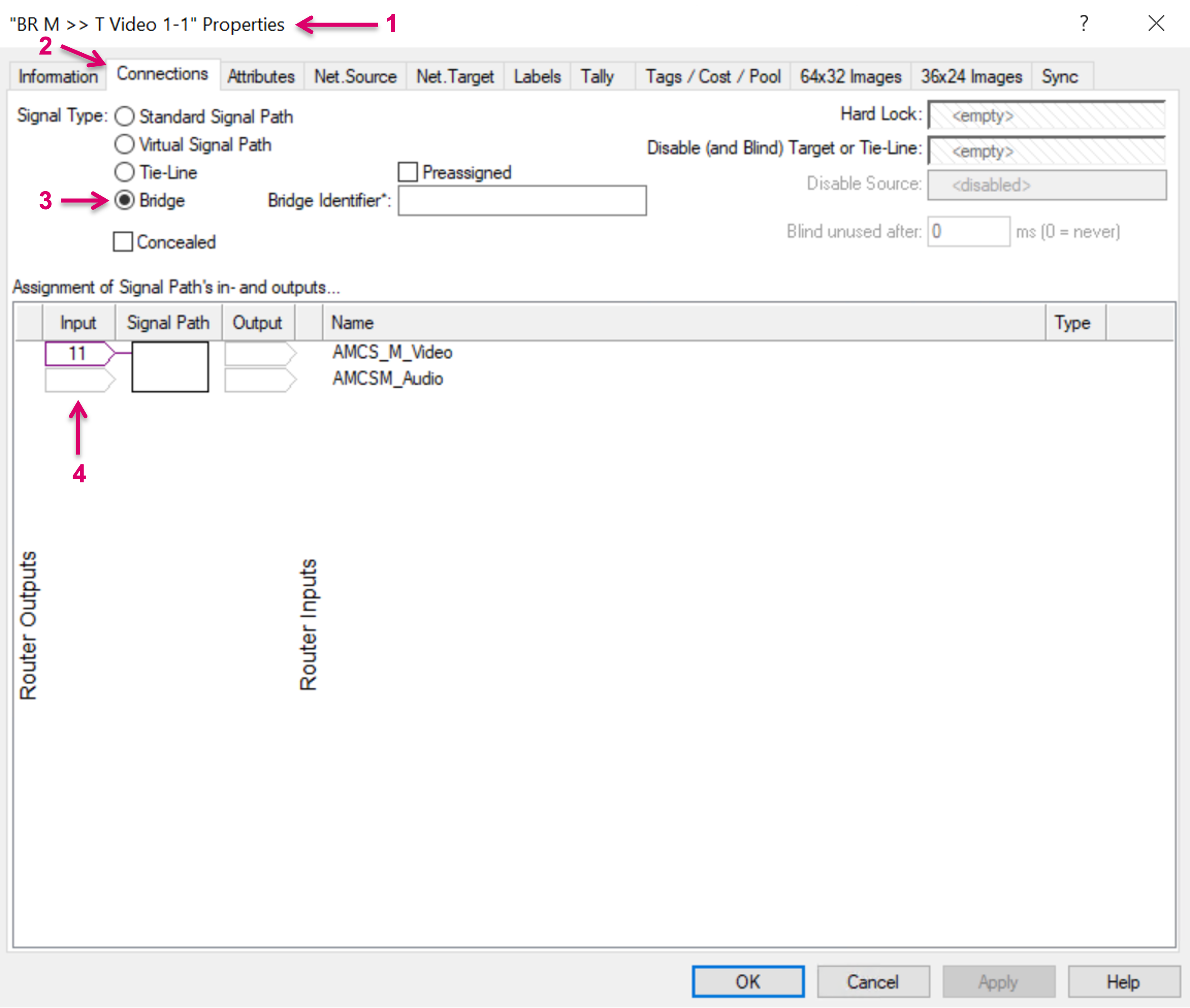
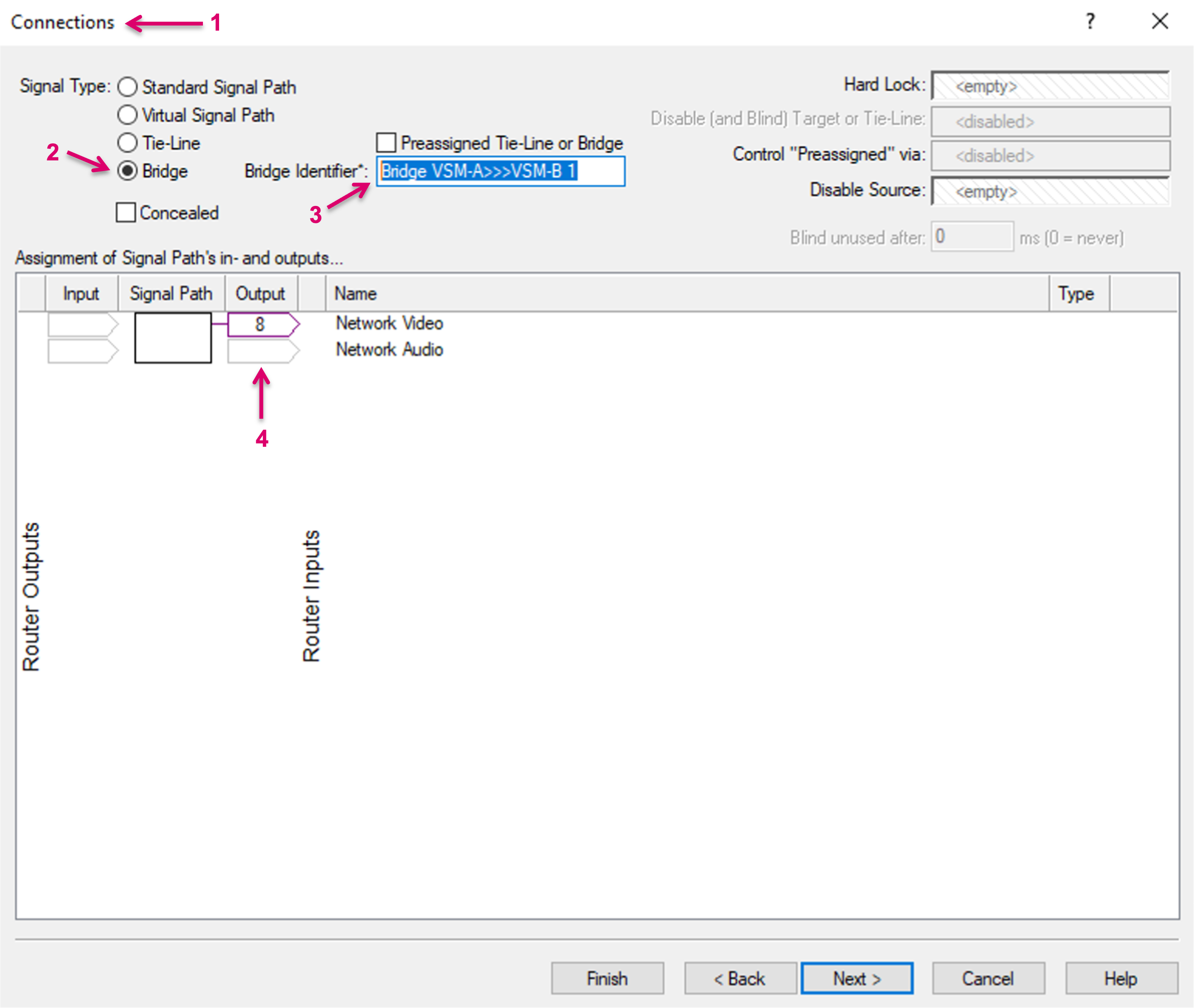
In the Signal Path properties (1), on tab Connections (2), select Signal type “Bridge” (3) and map this Signal Path to an available Target/Router Output slot on the respective layer (4). Proceed with OK.
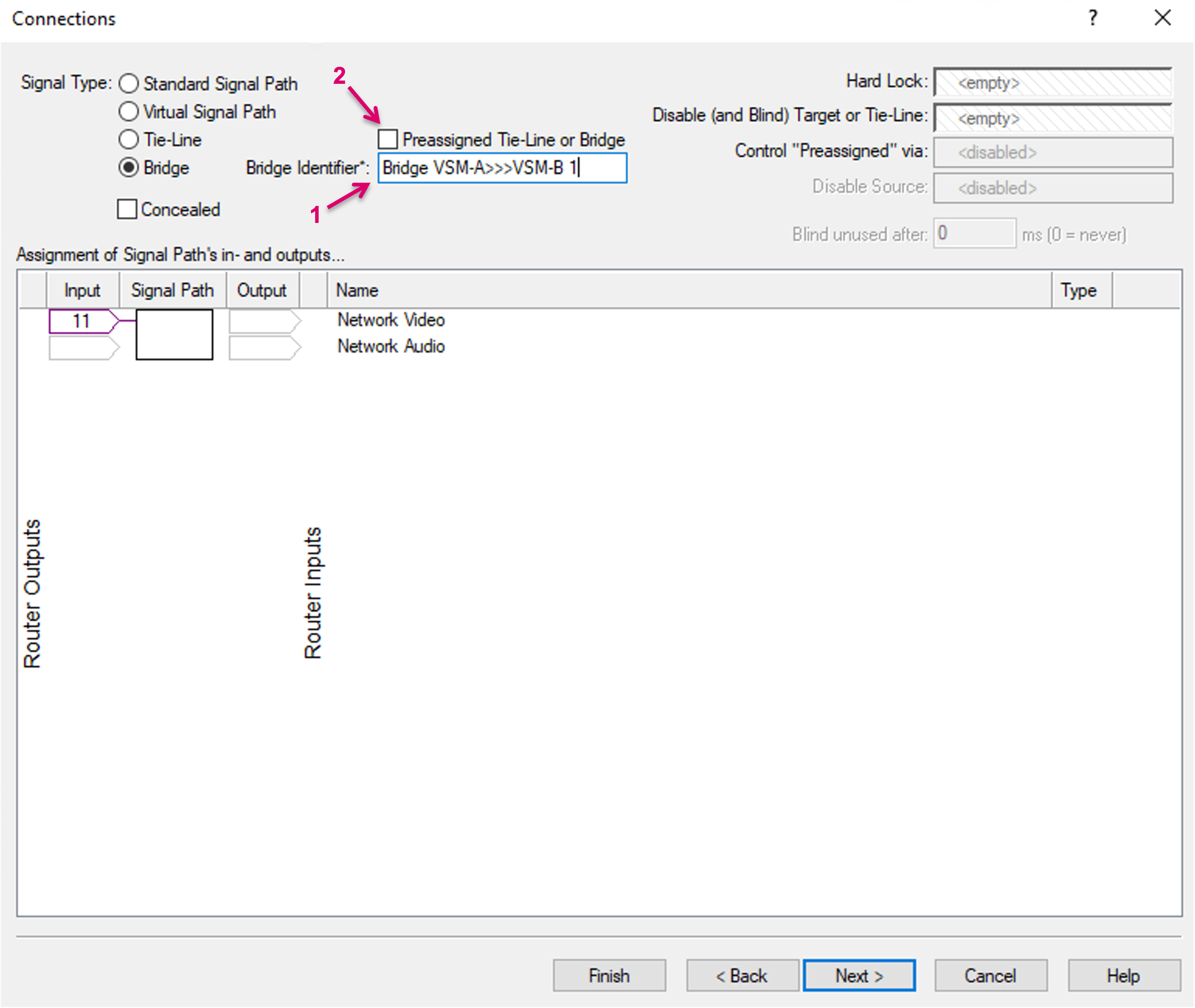
Select a unique “Bridge Identifier” label (1) which is recommended to be descriptive for the respective Bridge. Ideally the Bridge name and ID should contain information about from-layer-name>>> to-xyz. This may help overall transparency, in logs, etc.
While the original feature is based on a dynamic concept, where the system finds and uses free Bridges between systems when required, it may be desired to utilize the paths between the systems in a more deterministic way. For this, Bridges can also be Preassigned by selecting the respective option “Preassigned Tie-line or Bridge” (2). Please note the important, additional Notes in the box below. Proceed with Next.
- The Bridge Identifier is the essential path reference between the connected systems. For the pathfinding between the systems, it is mandatory that one Signal Path Bridge on the Provider side has a corresponding Signal Path Bridge on the Consumer side, with the exact same Bridge Identifier.
- The Bridge Identifier may only be used optional in an SDN environment together with Arista CXV, since in this scenario, the path identification can follow LLDP information in the network. It is still possible to make use of the Bridge Identifier to achieve a more transparent view of the bridge usage if monitoring Provider and Consumer system.
- Preassigned Bridges may only be assigned with physical Signals, no virtual Signals. (This will be enforced in a future release version)
- Preassigned Bridges may only be switched via Blind. (This will be enforced in a future release version)
The parallel use of preassigned and dynamic Bridges is possible. When using preassigned tie-lines it is the users responsibility to avoid duplicate Multicast addresses in the network.
- The use of preassigned Bridges in general bears the risk of duplicate Multicast routes into the network, if the same network stream is assigned to multiple Bridges. This may lead to malfunction. This scenario must be avoided by respective caution in operation and when configuring workflows.
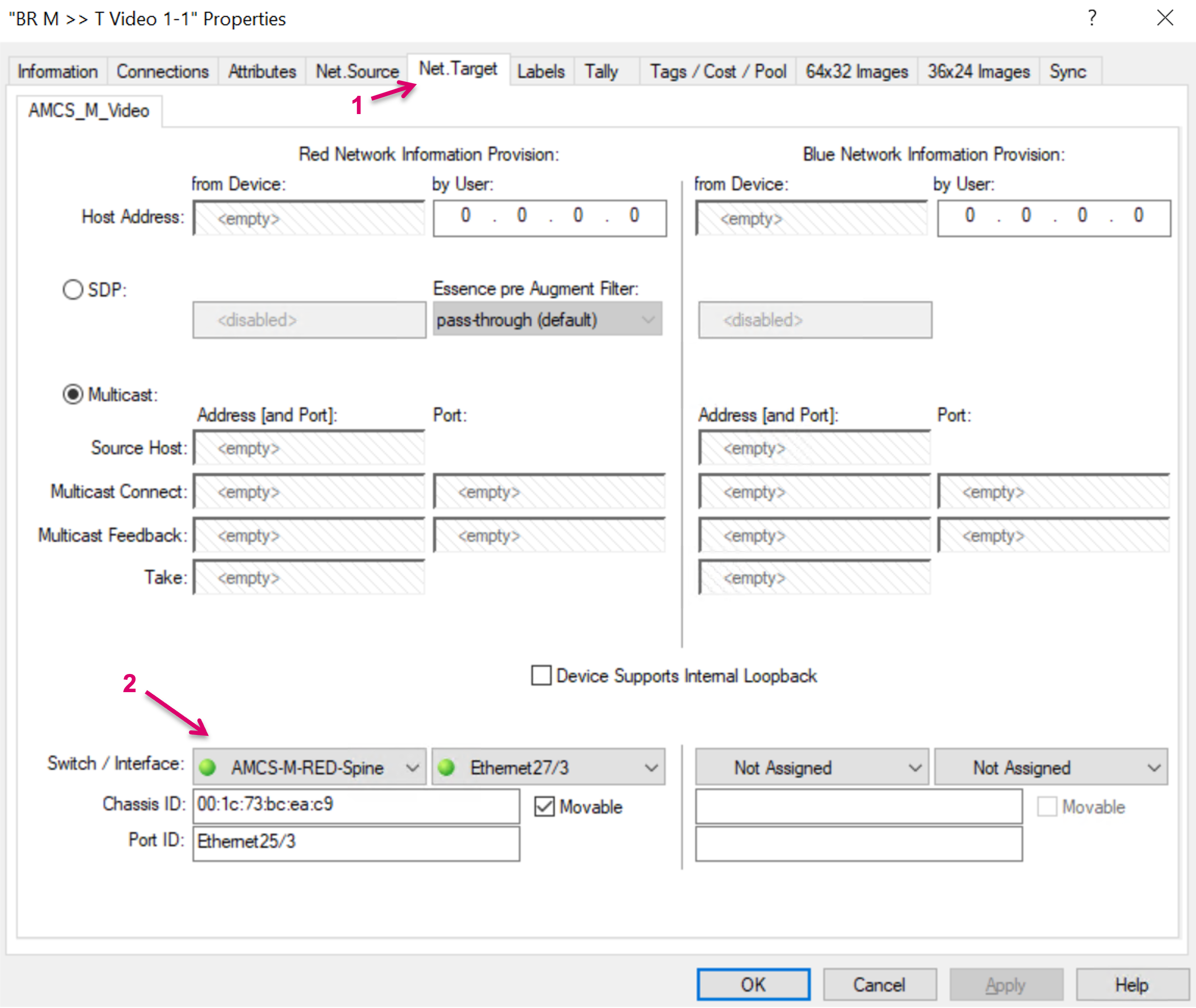
Proceed to tab Net. Target (1) and assign the respective Switch interface (2) for this Bridge. Please note that multiple Bridges may be assigned to the same Switchport. The possible number of bridges must be calculated based on the maximum available link bandwidth, divided by the maximum bandwidth expected of any signal that is going to be shared. Proceed with OK or Finish.
Repeat above steps to create further Signal Path Bridges.
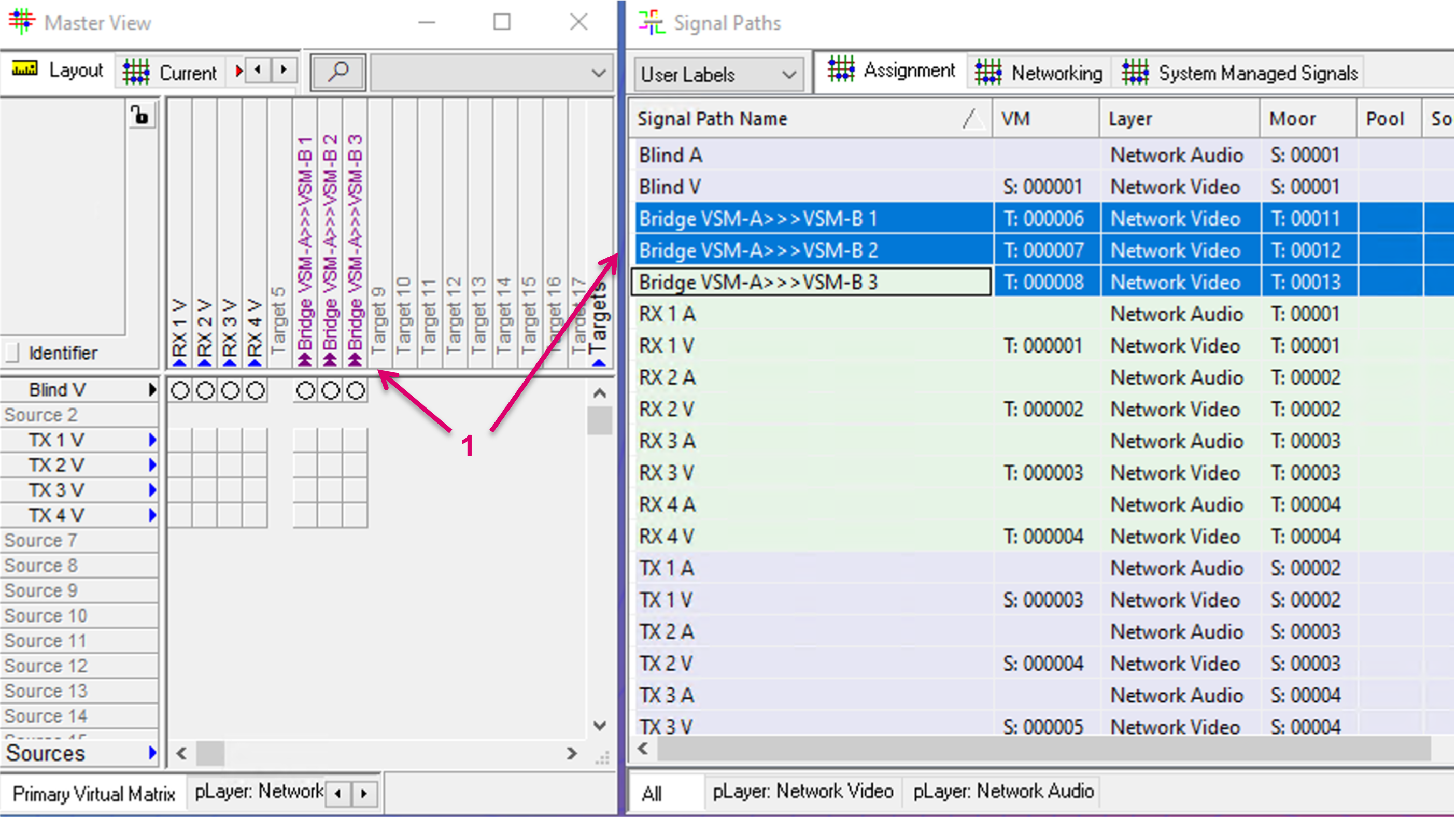
Once the Bridge Signal(s) are created, they also show on the respective layer and can be dragged and dropped into the Primary Virtual Matrix view (1).
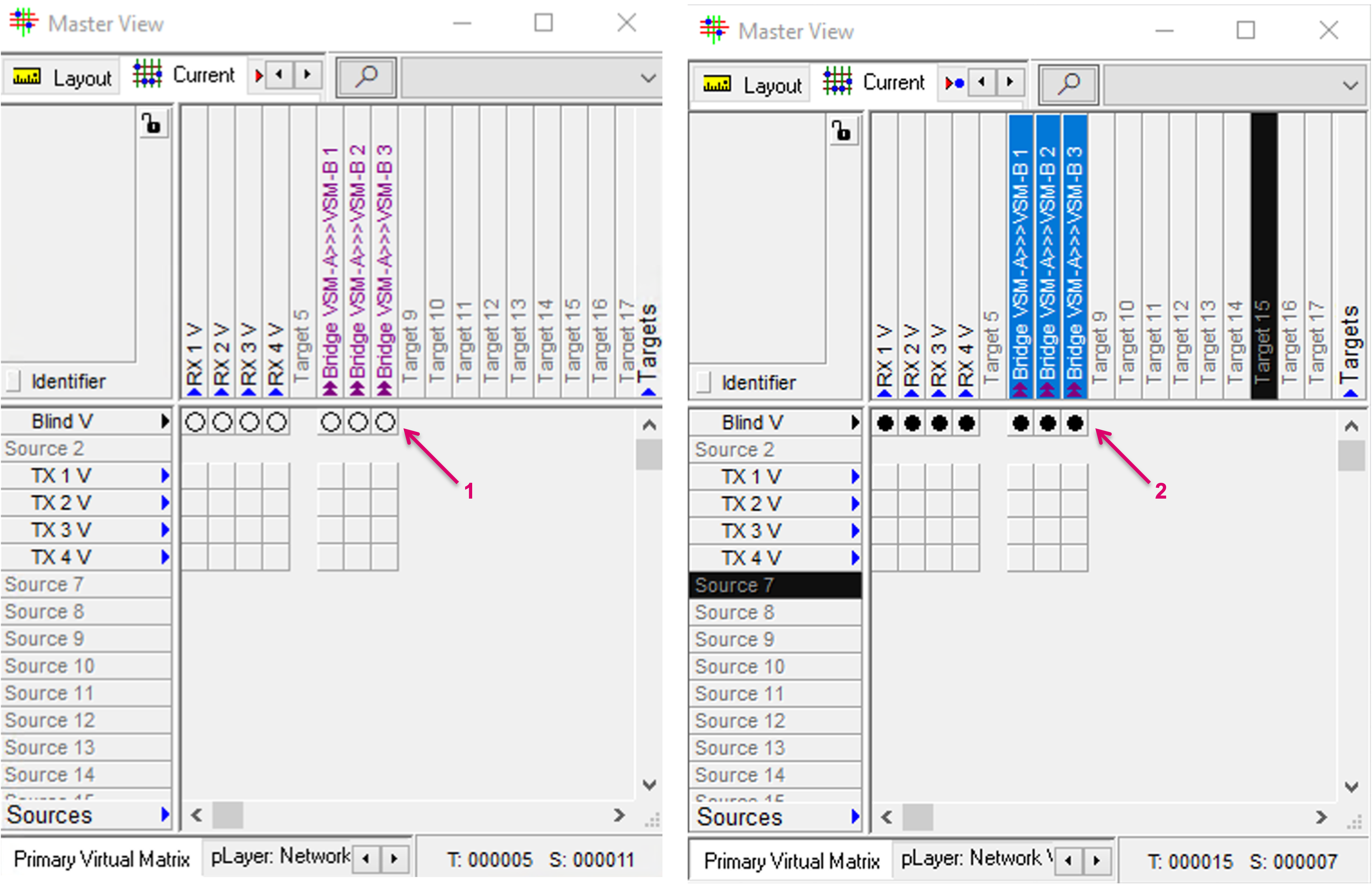
Before the newly created bridges can be used by the system, a defined routing state is required. Therefore, same as for Tie-lines, first assign Blind to the new Bridge targets. To do so, hold Ctrl.+Shift and set the crosspoint in the matrix view (via Current tab).
Share Source Signal Paths
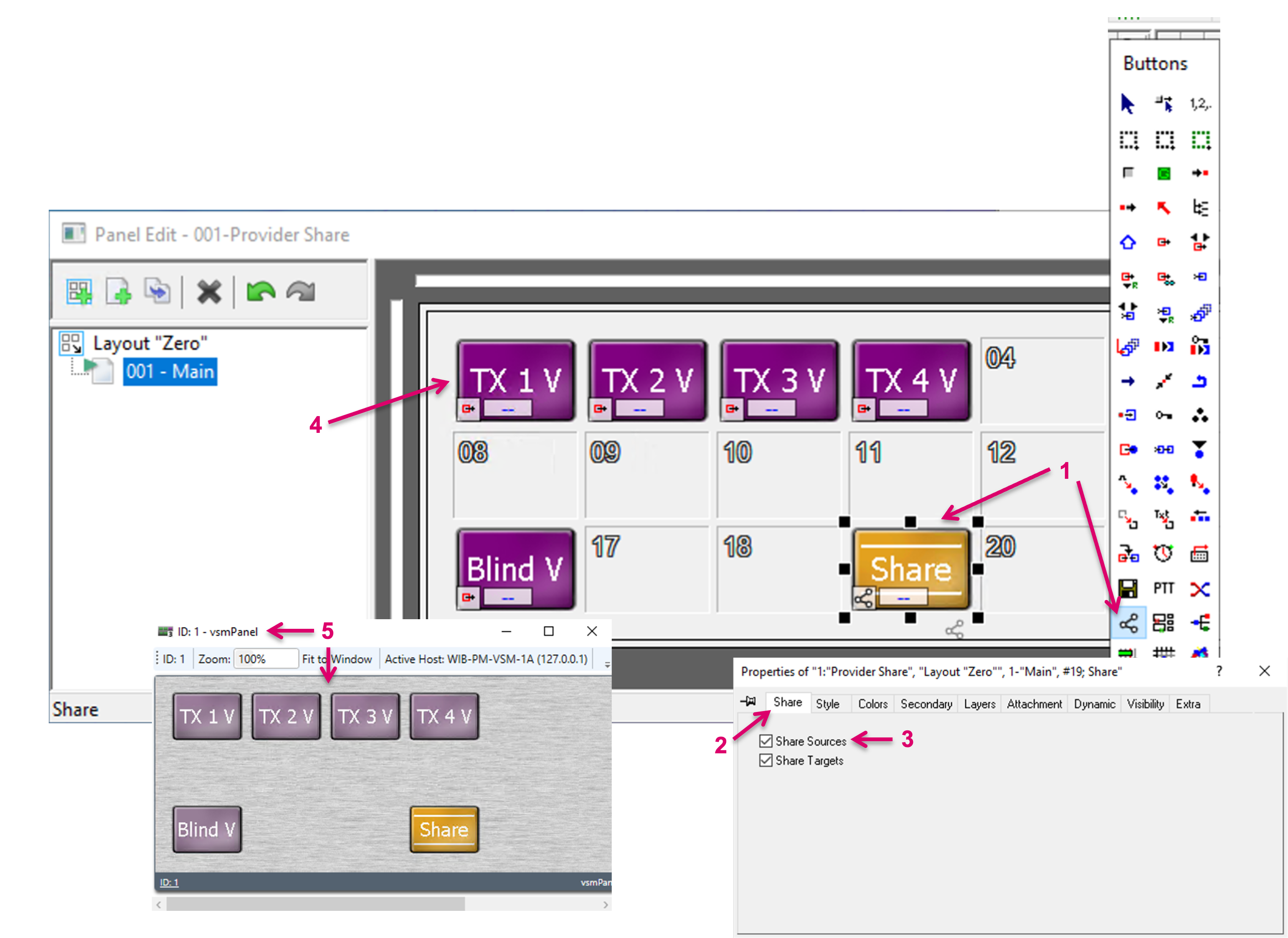
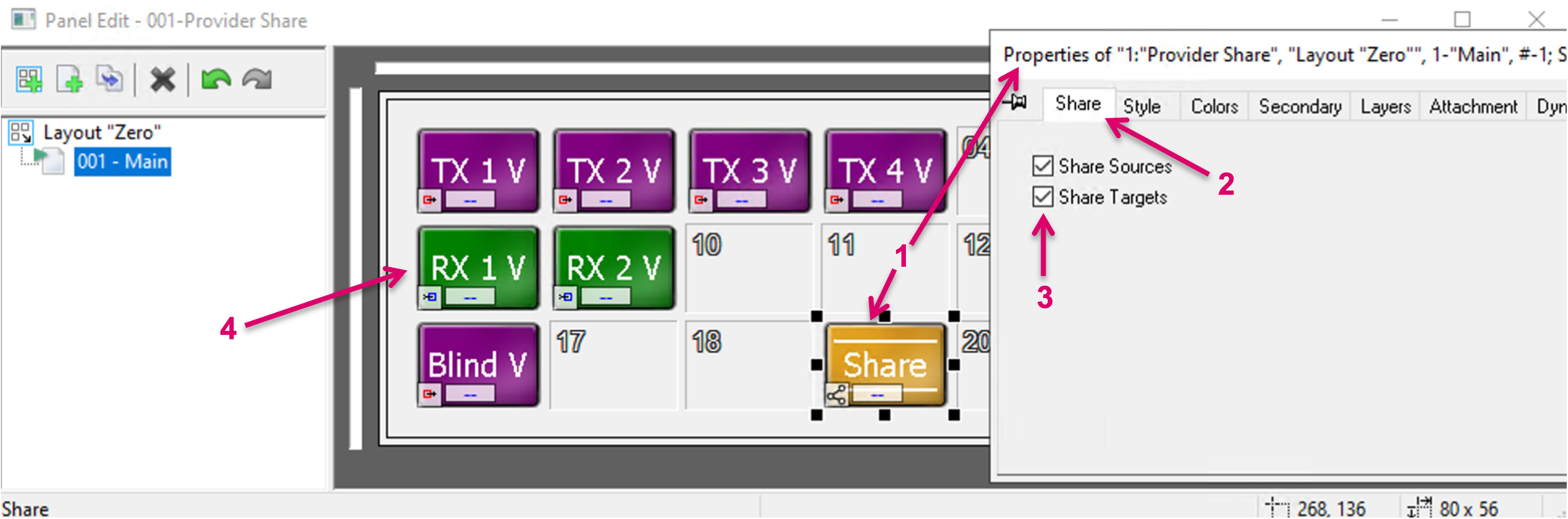
Once Bridges are created, the actual sharing of Sources can be triggered via a VSM panel UI. To configure a Panel accordingly, navigate to the respective Panel and page in Editor mode. Assign the dedicated Share function from the toolbox to one button (1). Once assigned, navigate to tab Share in the Button Properties (2) and select “Share Sources” (3). Drag and drop Source Signals, that potentially shall be shared with a remote server, to the same Panel (4).
Once configured, open the respective panel UI (5).
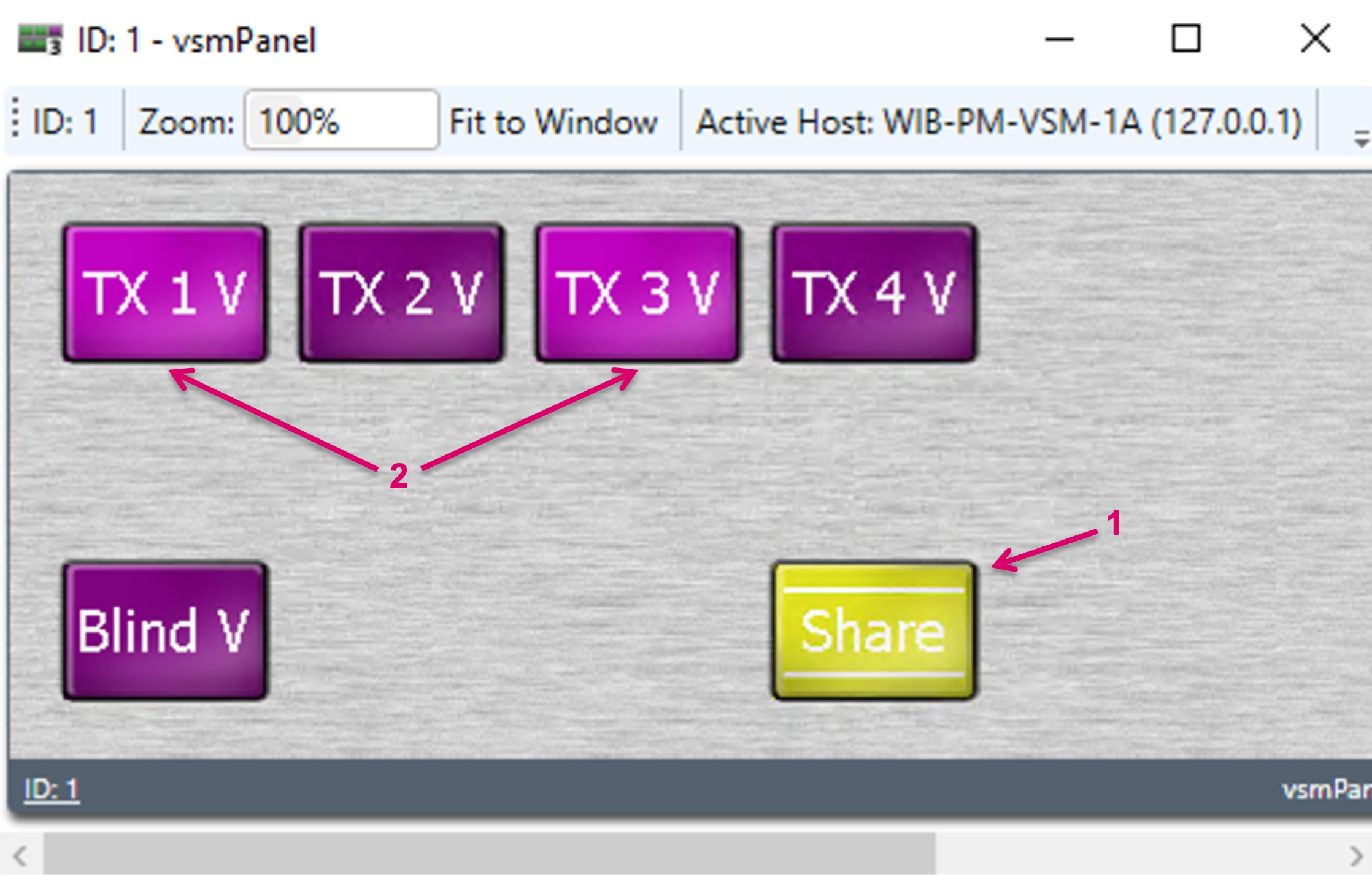
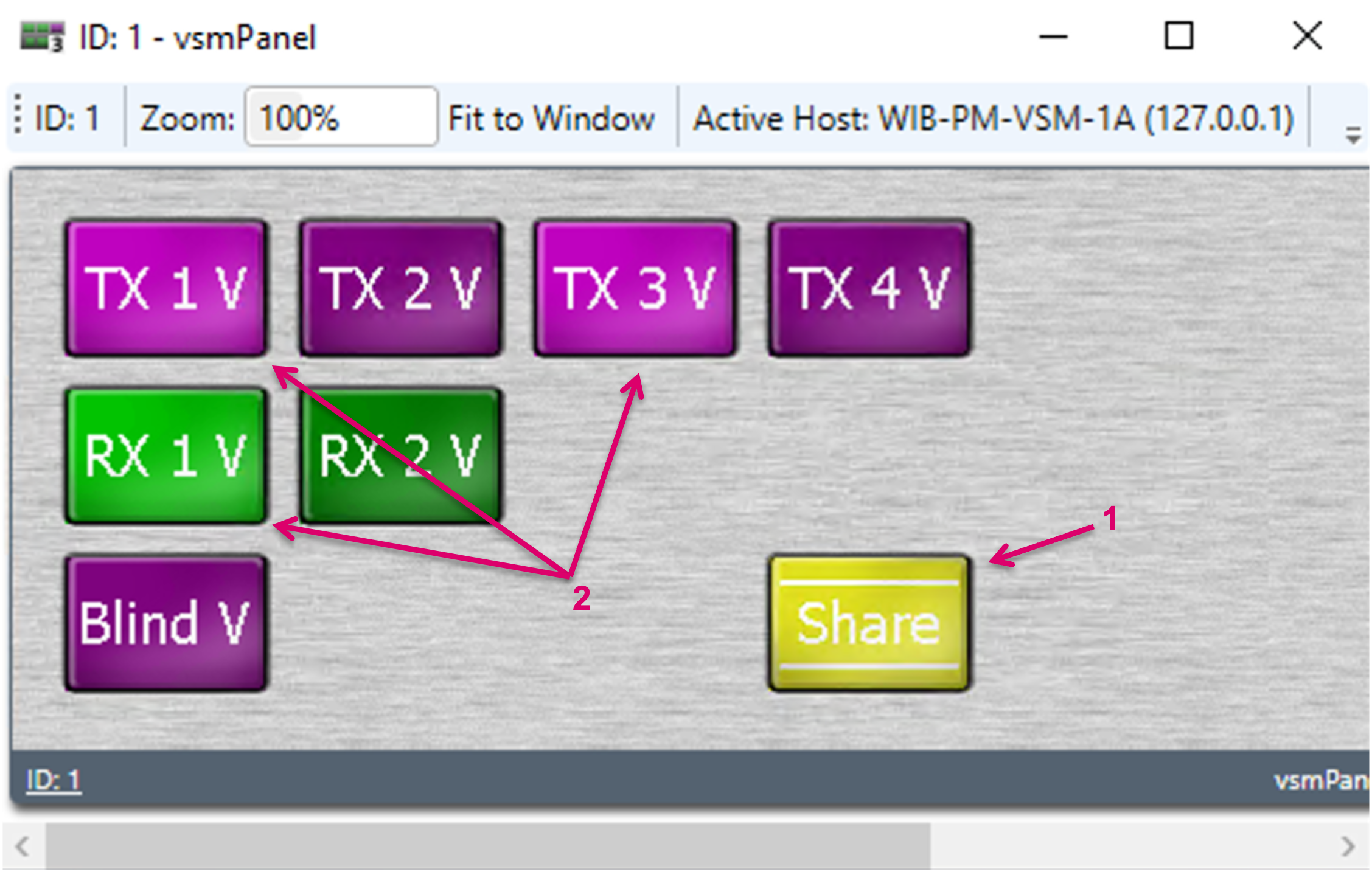
First, press the Share button (1). It will indicate its active state by starting to blink. Then select one or multiple Sources to be shared (2). The selected Sources will immediately show on the consumer side as available Sources. Finish the Share operation by selecting the Share button again (1). The button will stop blinking.
The shared resources will only utilise a Bridge, and consume bandwidth in a network environment, if actually in use on a consumer side. So, as long as a shared Source is not switched to any target on the remote Server, the share will not trigger a physical Signal flow.
Share Target Signal Paths
Once Bridges are created, the actual sharing of Targets can be triggered via a VSM panel UI. To configure a Panel accordingly, navigate to the respective Panel and page in Editor mode. Assign the dedicated Share function from the toolbox to one button (1). Once assigned, navigate to tab Share in the Button Properties (2) and select “Share Targets” (3). Drag and drop Target Signals, that potentially shall be shared with a remote server, to the same Panel (4).
Once configured, open the respective panel UI and first, press the Share button (1). It will indicate its active state by starting to blink. Then select one or multiple Sources to be shared (2). The selected Target will immediately show on the consumer side as available Target. Finish the Share operation by selecting the Share button again (1). The button stops blinking.
The shared resources will only utilise a Bridge and, in a network environment, consume bandwidth, if in fact in use on a consumer side. So, as long as a shared Target gets no Remote Server Source assigned, the share will not trigger a physical Signal flow.
- In order that a Consumer can make use of a shared Target and assign a local Source, outgoing Bridges must be configured and available/free on the Consumer side as well.
- While a Target-share may effectively result in a Source being shared from the Remote system, the respective Remote Source does not need to be shared as Source from the Remote System in a separate step. This step is automatically handled by the system internally. Such Sources won’t be shown as dedicated shared Sources on the other side. Of course this only applies if the source wasn’t already shared manually.
- A shared Target can only be switched to a local source. So a Target shared from System-A to System B can only be switched to a local Source in System-B but not to a shared Source of System-A.
Share Target Lock
If a Target is shared, the corresponding Target Lock state is shared as well. The Provider is the owner of a shared Target Lock and can lock and unlock at any time. If locked on the Provider, the Consumer will see the Lock state but cannot unlock the Target. The Consumer can lock and unlock the same Target locally though. The lock state that was initiated by the Consumer, is not shared back to the Provider.
The shared Lock state is a Target lock only, no Signal Path lock. Means, if e.g., a virtual Signal is assigned to a shared Target and subsequently locked, the Virtual to Target assignment is locked, while the Input of the respective Virtual Signal can still be switched.
Receive and map Source Tally from Consumer
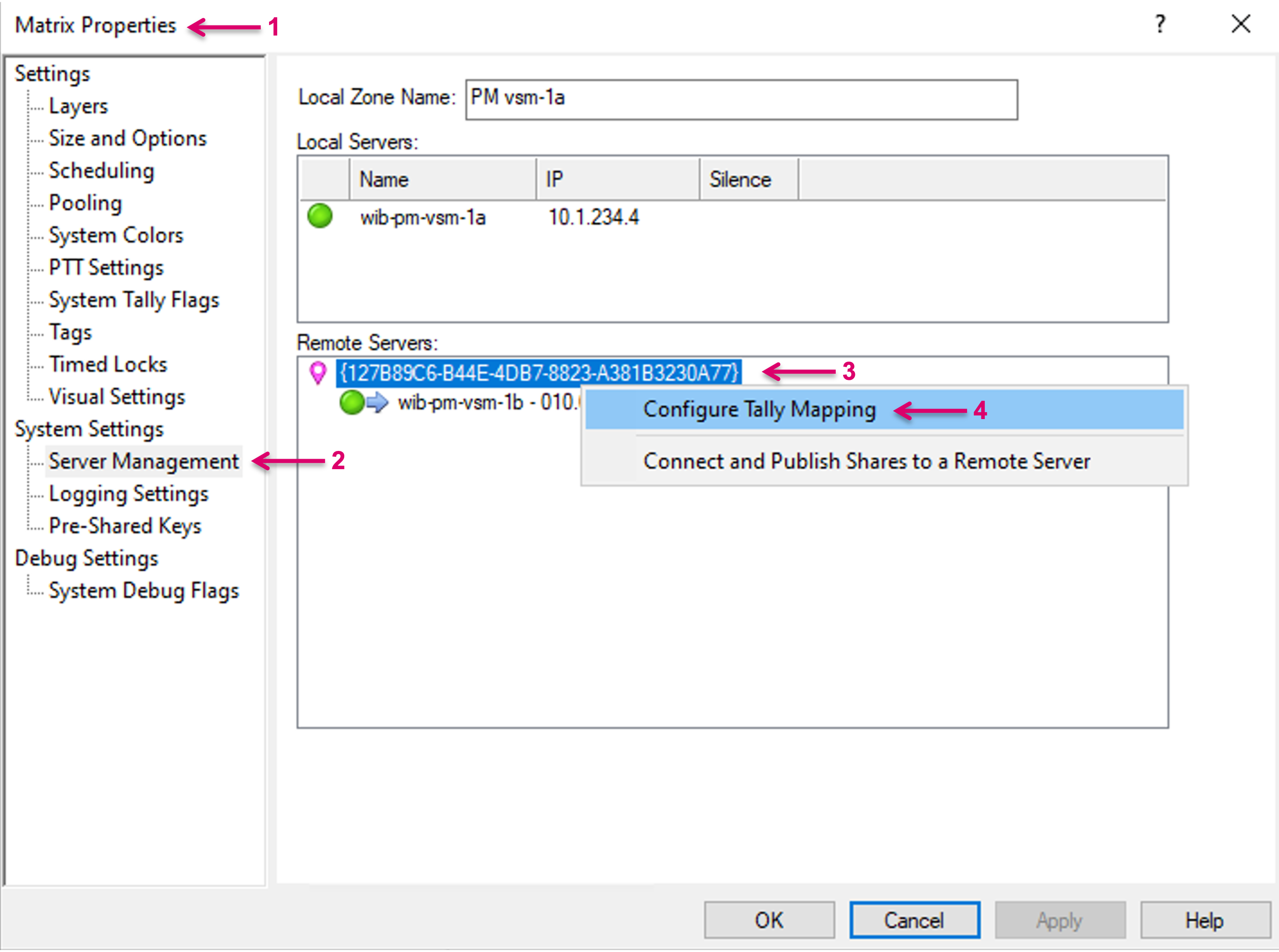
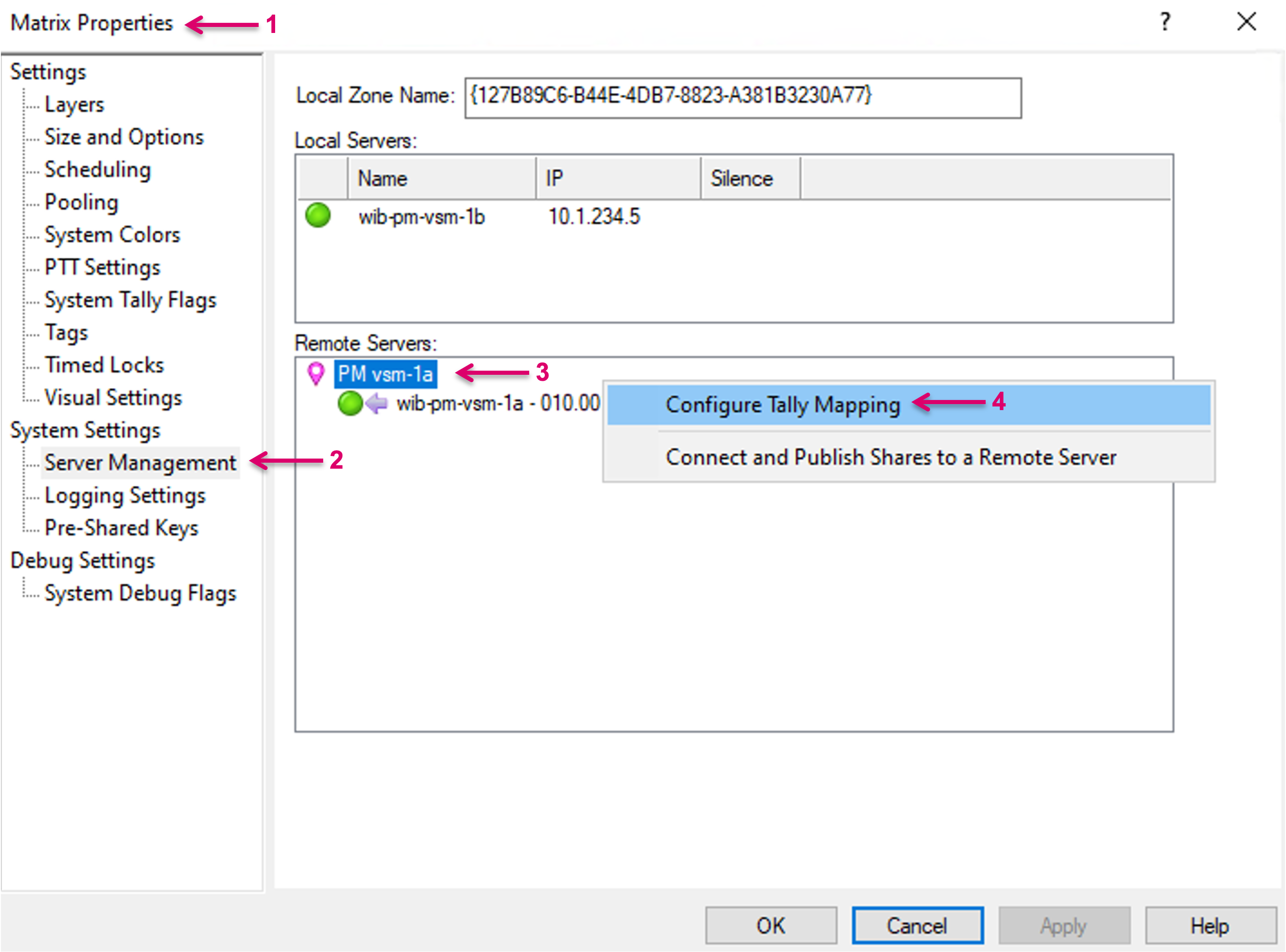
Optional the Provider can receive Tally states for his shared Sources from the Consumer. To enable this option, navigate to Matrix Properties (1) and to SubMenu Server Management (2). Make a right-mouse-click on the Zone ID of the respective Remote side (3), from where Tally states shall be received. In the pop-up menu, select Configure Tally Mapping (4).
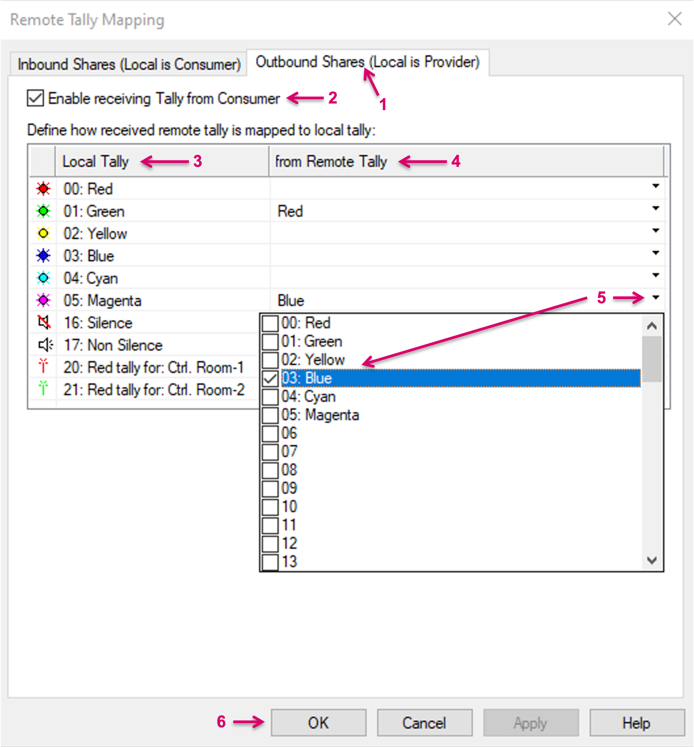
In the opening Dialogue navigate to tab Outbound Shares (Local is Provider) (1). Check the option Enable receiving Tally from Consumer (2).
The table below allows to map the local system Tally levels to the received Tally. The column “Local Tally” (3) lists all labeled, local Tally levels. The column “from Remote Tally” (4) represents the Tally levels that can be received. By click on the small arrow in any of the “from Remote Tally” cells, it can be selected which received Tally status shall be mapped to which local Tally level (5). An n:1 assignment is possible. Finish the configuration with OK (6).
vsmShare Consumer
A vsmShare consumer can see and utilize shared resources from a Remote Provider system. From an operational point of view, these shares appear and can just be used similar to its own local resources. Shared Sources from a Provider can be routed to local Targets and local Sources can be routed to shared Provider Targets.
Re-sharing must be avoided by respective measures in the workflow configuration process to avoid potential loopbacks.
Connect to a Remote Server
To share signal resources, first a connection to a Remote Server must be established. Remote Server connections are administrated in System/Matrix Properties (1). Click System Properties and navigate to System Settings and Server Management (2) via the left-hand menu column. The local cluster Servers are listed under Local Servers and the Local Zone Name is displayed on top (3).
A remote connection is initiated from the Provider side. Once a Provider has sent a request to “Connect and Publish Shares”, its Zone Name (1), Server name and address (2) are showing up on the respective Remote system.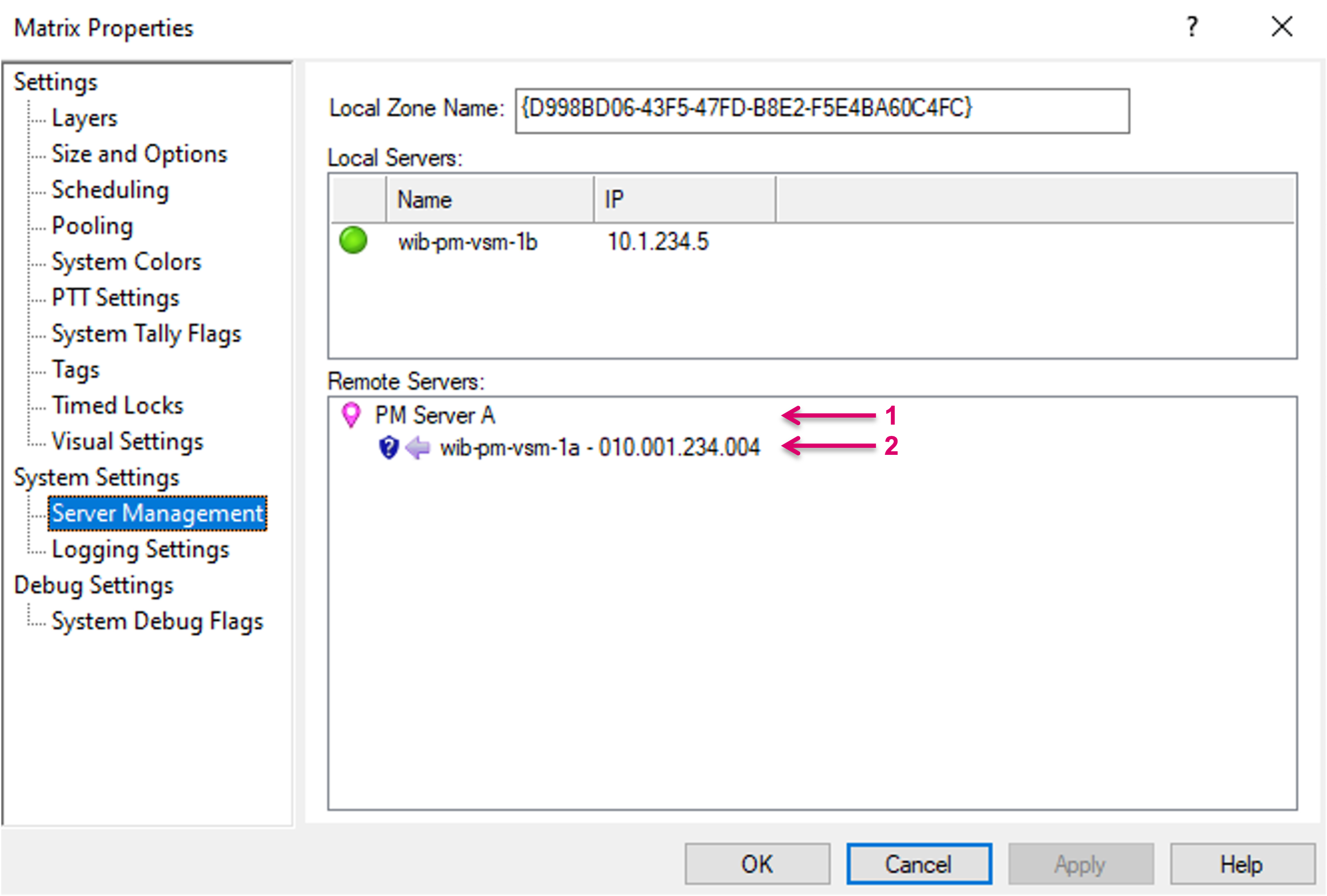
To accept the connection on the Consumer, right-mouse-click on the respective entry (1) and in the pop-up window select “Enable shares from this Server” (2).
Once the connection is successfully established, the status indicator will show green (1).
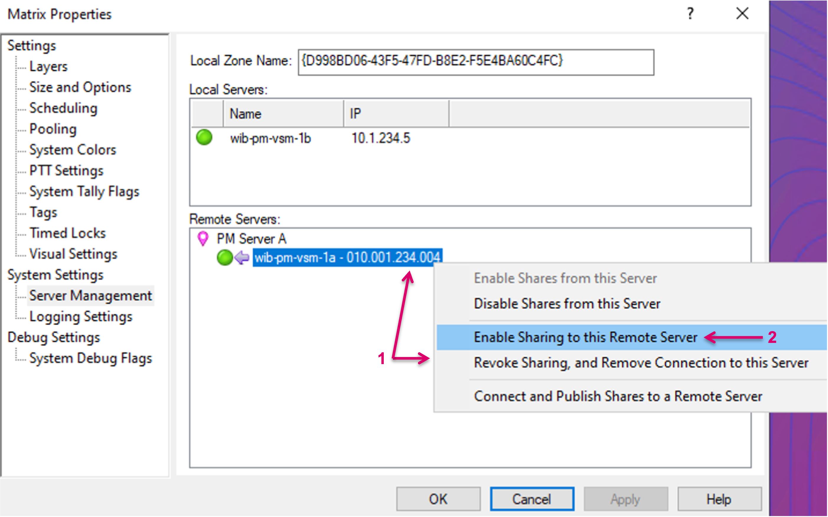
Once the incoming share connection is established, in return it is now possible to also initiate a Provider connection back to the Remote System. To do so, right-mouse-click on the Remote Server entry (1) and select “Enable sharing to this Remote Server” (2).
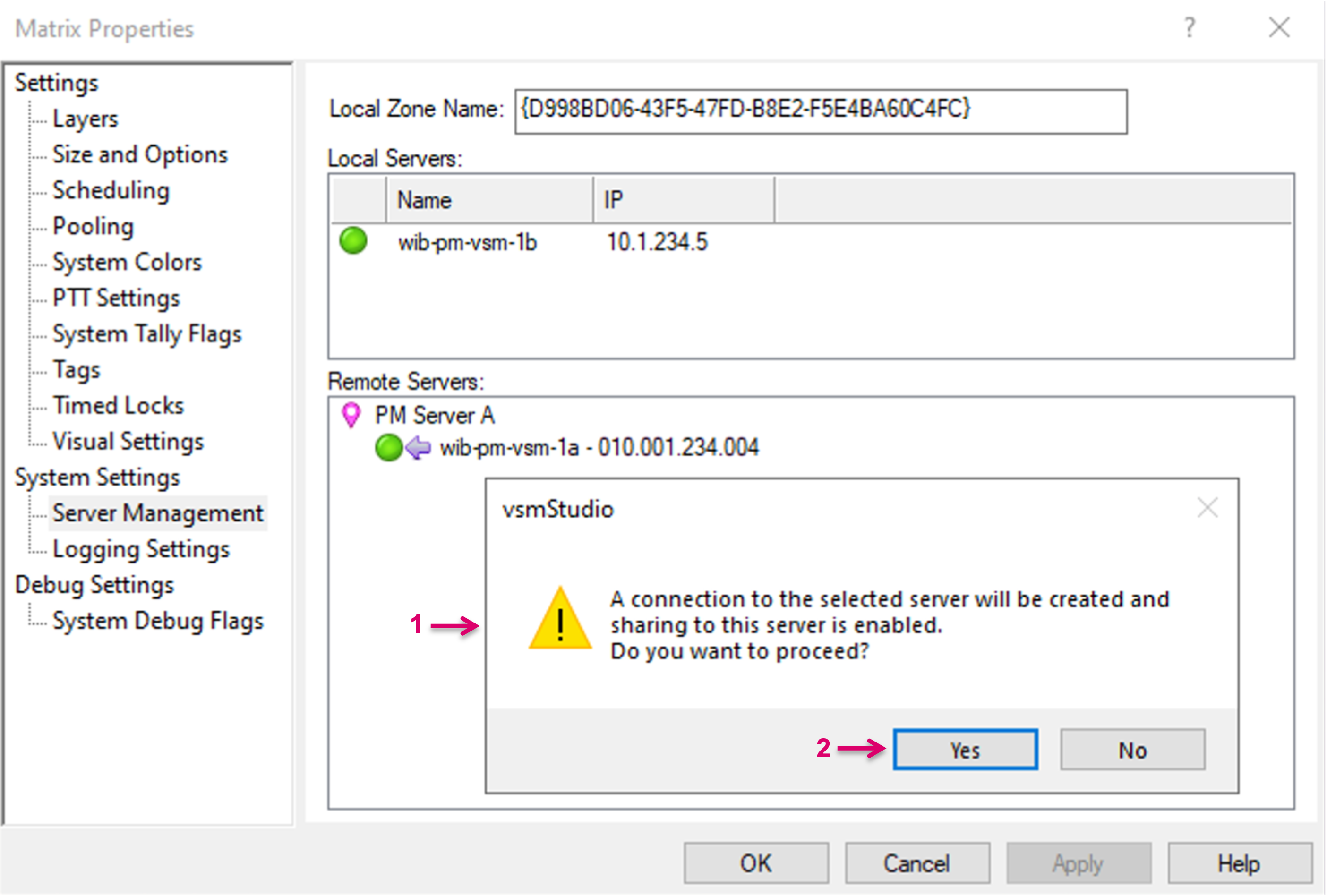
A pop-up window (1) will come up. To proceed, confirm with “Yes” (2).
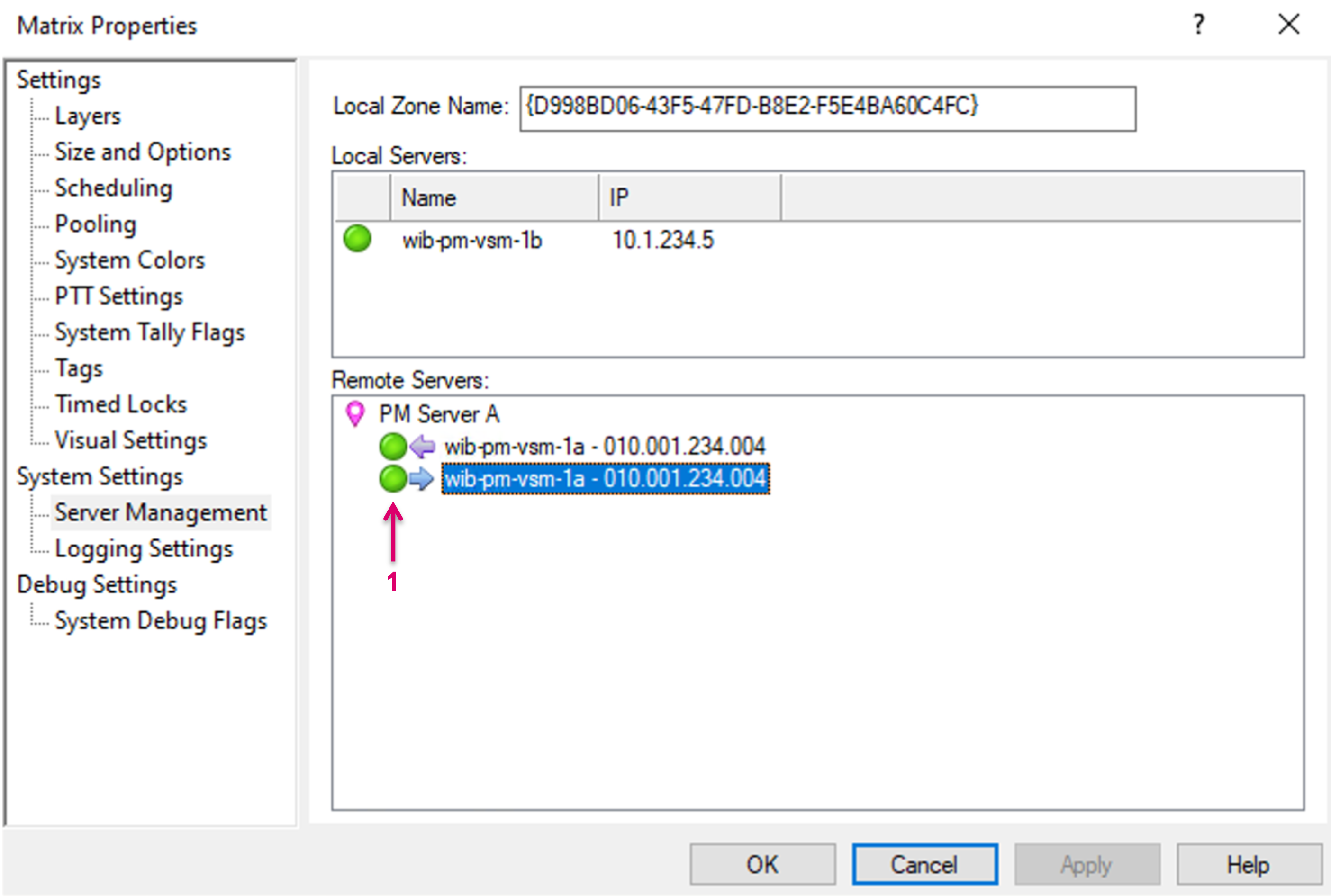
Once the connection is confirmed and established the respective entry and status will show (1).
Create Signal Path Bridges
Before remote Source or Target Signal Paths can be received and utilized, it is mandatory to create “Bridges”, which represent the network Tie-lines between the connected systems. There is no differentiation between Bridges for vsmShare Sources or vsmShare Targets.
Bridges must be created on both, Provider (as Target) as well as Consumer (as Source) System separately but with the same Bridge Identifier, as explained in more detail below.
The number of available Bridges defines the possible number of parallel Signal shares. Please note that the system does not differentiate signal formats, so the number of bridges must be calculated based on the maximum available link bandwidth, divided by the maximum bandwidth expected of any signal that is going to be shared. In a system with one single house-format this is easy, in case of a mixed format infrastructure, you will need to calculate with the higher bandwidth to avoid oversubscription on the network links.
To create a Bridge, open the Signal Paths list (1). Right click into the window and select “New Signal Path” (2).

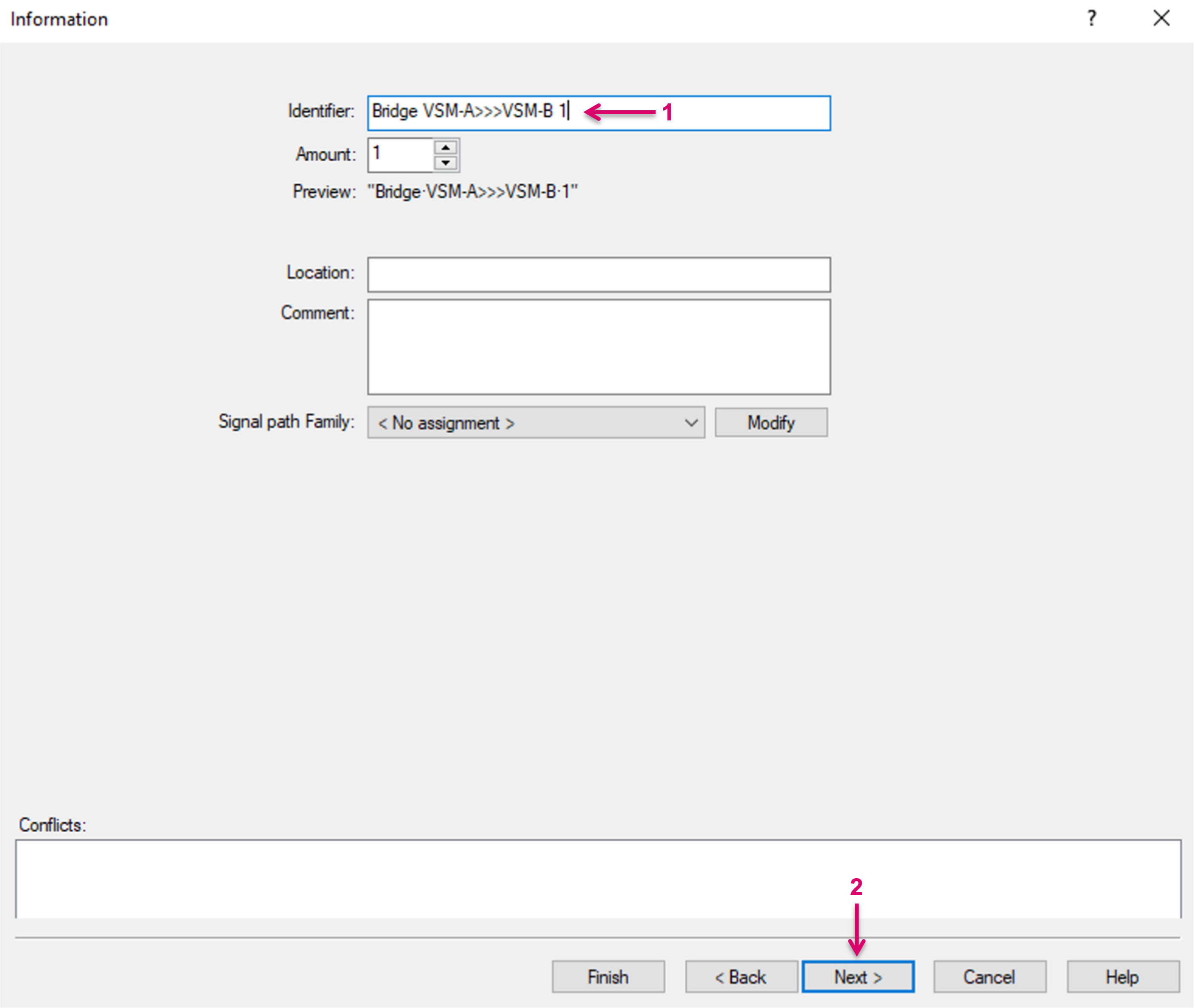
Assign an Identifier name (1) and proceed with “Next” (2).
In the Signal Path properties, on tab Connections (1), select Signal type “Bridge” (2) and assign the Bridge Identifier name (must be identical with the Identifier name set on the Provider system, for the same Transport Tie-line between both Systems!) (3). Then map this Signal Path to an available Source/Router Input slot on the respective layer (4).
Proceed with Next.
The Bridge Identifier is the essential path reference between the connected systems. For the pathfinding between the systems, it is mandatory that one Signal Path Bridge on the Provider side has a corresponding Signal Path Bridge on the Consumer side, with the exact same Bridge Identifier name.
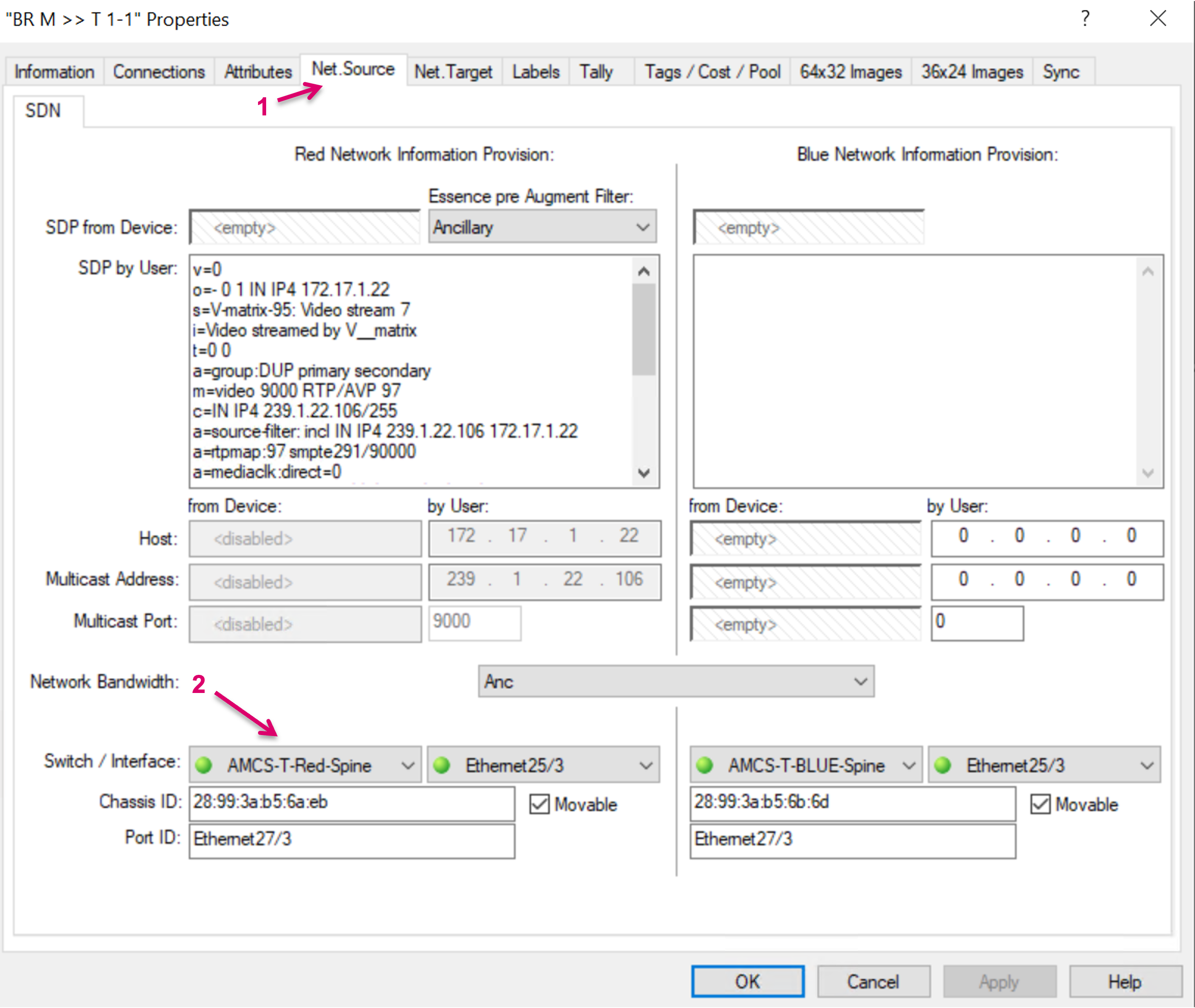
Proceed to tab Net. Source (1) and assign the respective Switch interface (2) for this Bridge. Please note that multiple Bridges may be assigned to the same Switchport. The possible number of bridges must be calculated based on the maximum available link bandwidth, divided by the maximum bandwidth expected of any signal that is going to be shared. Proceed with OK or Finish.
Repeat above steps to create further Signal Path Bridges.
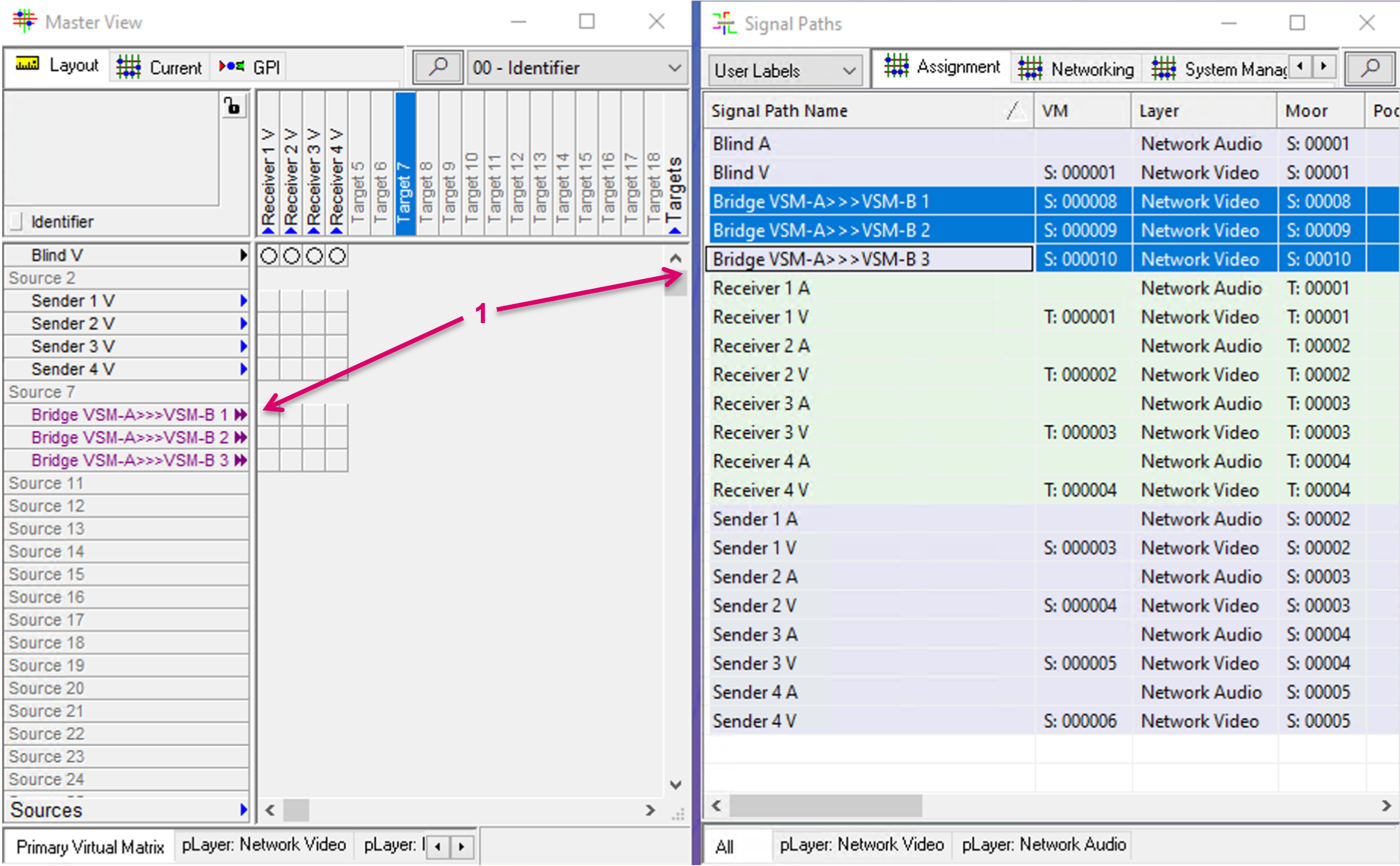
Once the Bridge Signal(s) are created, they also show on the respective layer and can be dragged and dropped into the Primary Virtual Matrix view (1).
Utilise shared resources from Provider
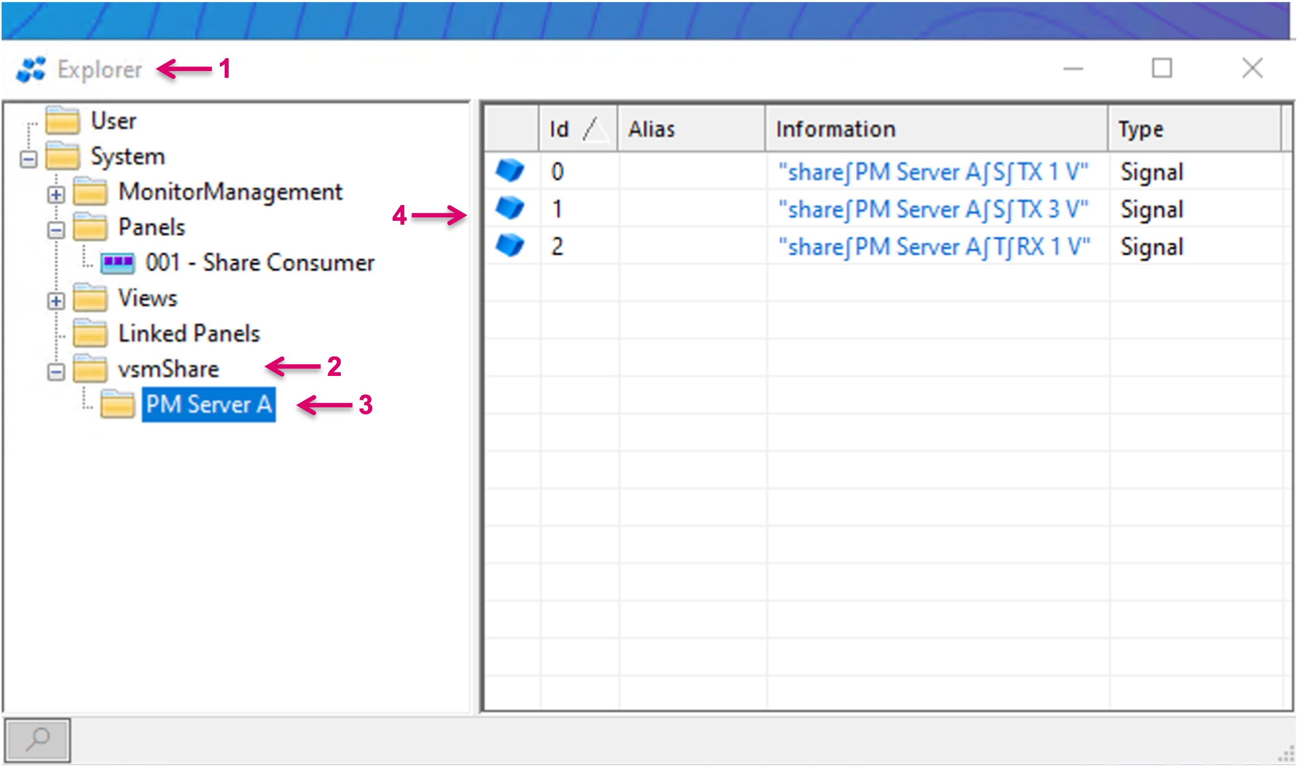
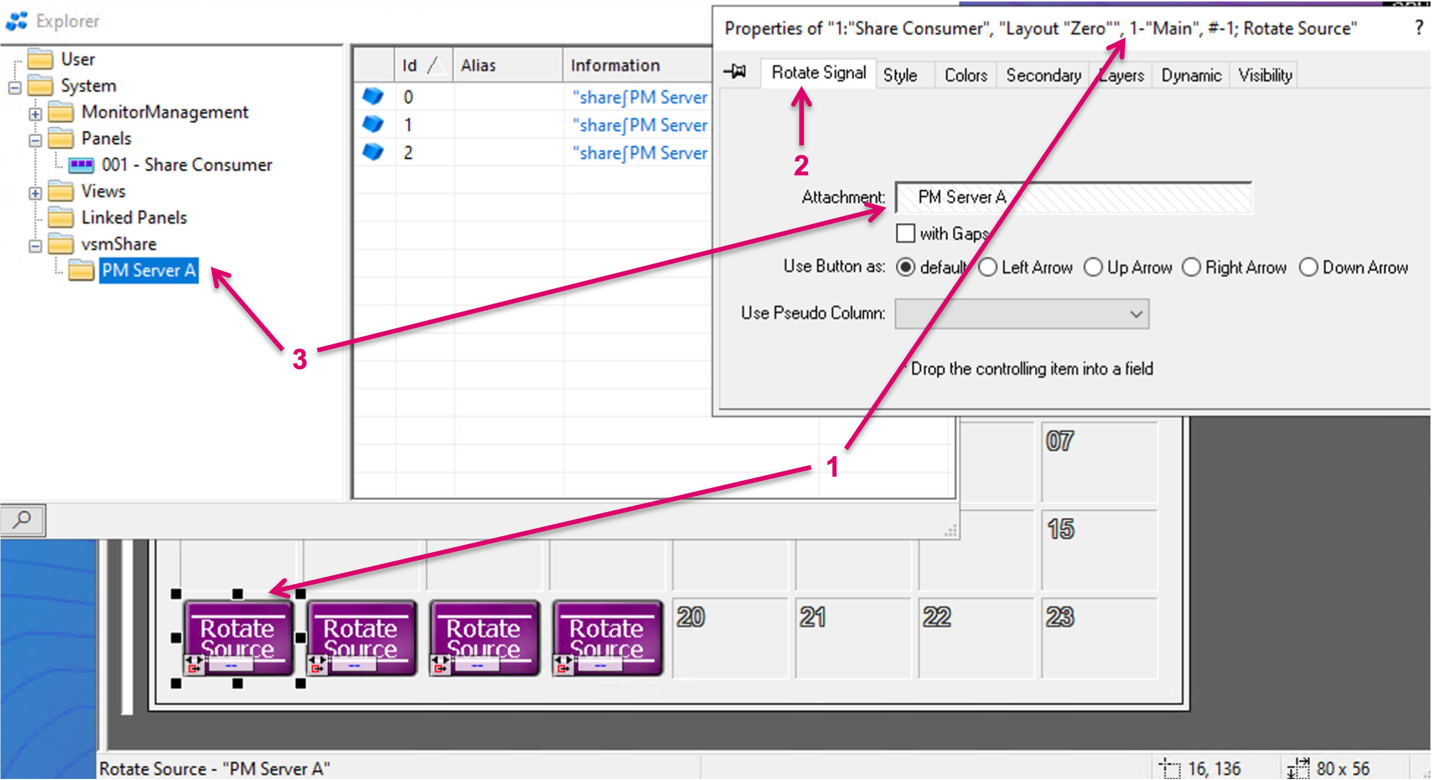
In order to utilise and route shared Source or Target resources from a Provider, the respective Signal Paths must be assigned to panel buttons. To do so, first navigate to the Explorer menu (1). Navigate to submenu vsmShare (2) and select the respective entry of the providing Remote System (3). Current shares from the Provider are listed in the righthand area of the window.
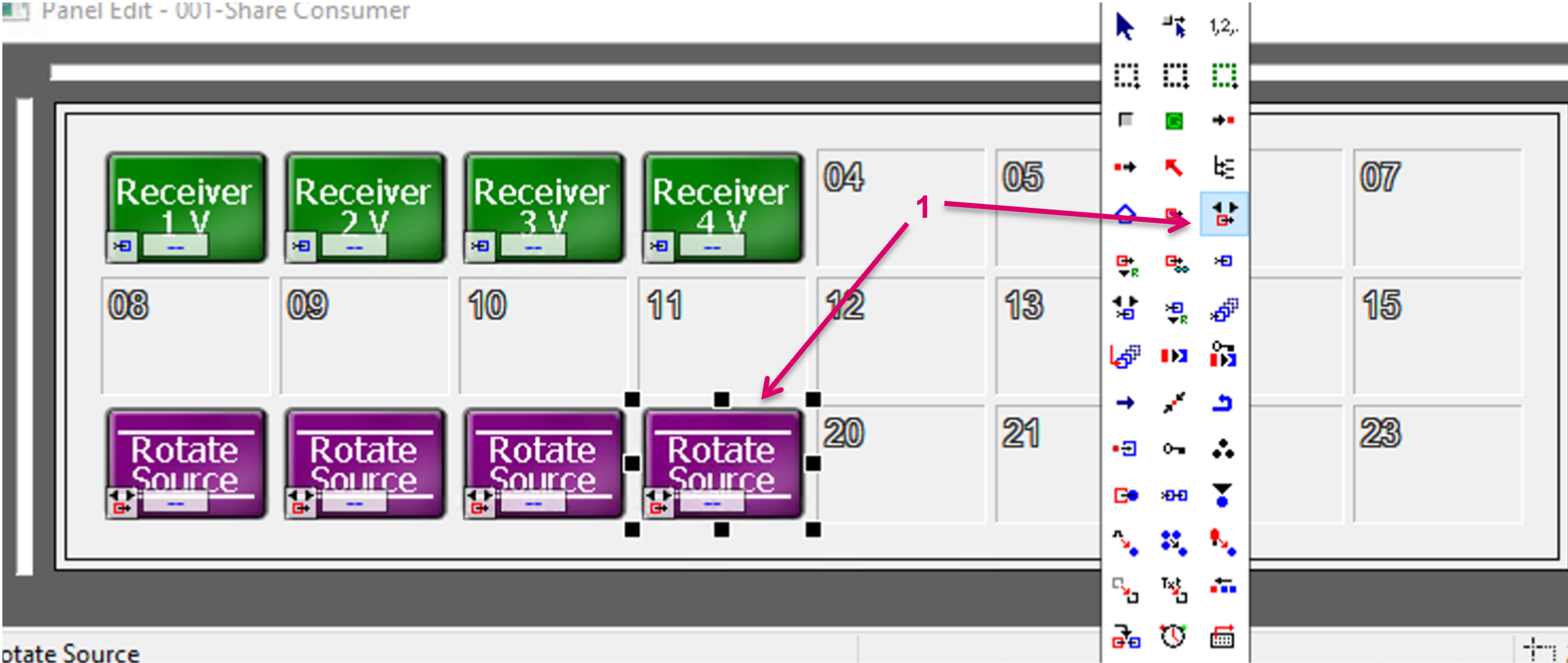
Beside this, open the desired Panel layout in the Panel editor and, for shared Sources, add multiple Rotate Source buttons to a page (1).
Select the first Rotate Source button and in the button Properties window (1), navigate to tab Rotate Signal (2). Then drag and drop the vsmShare/Remote System folder node from the Explorer view into the attachment area of the button properties (3).
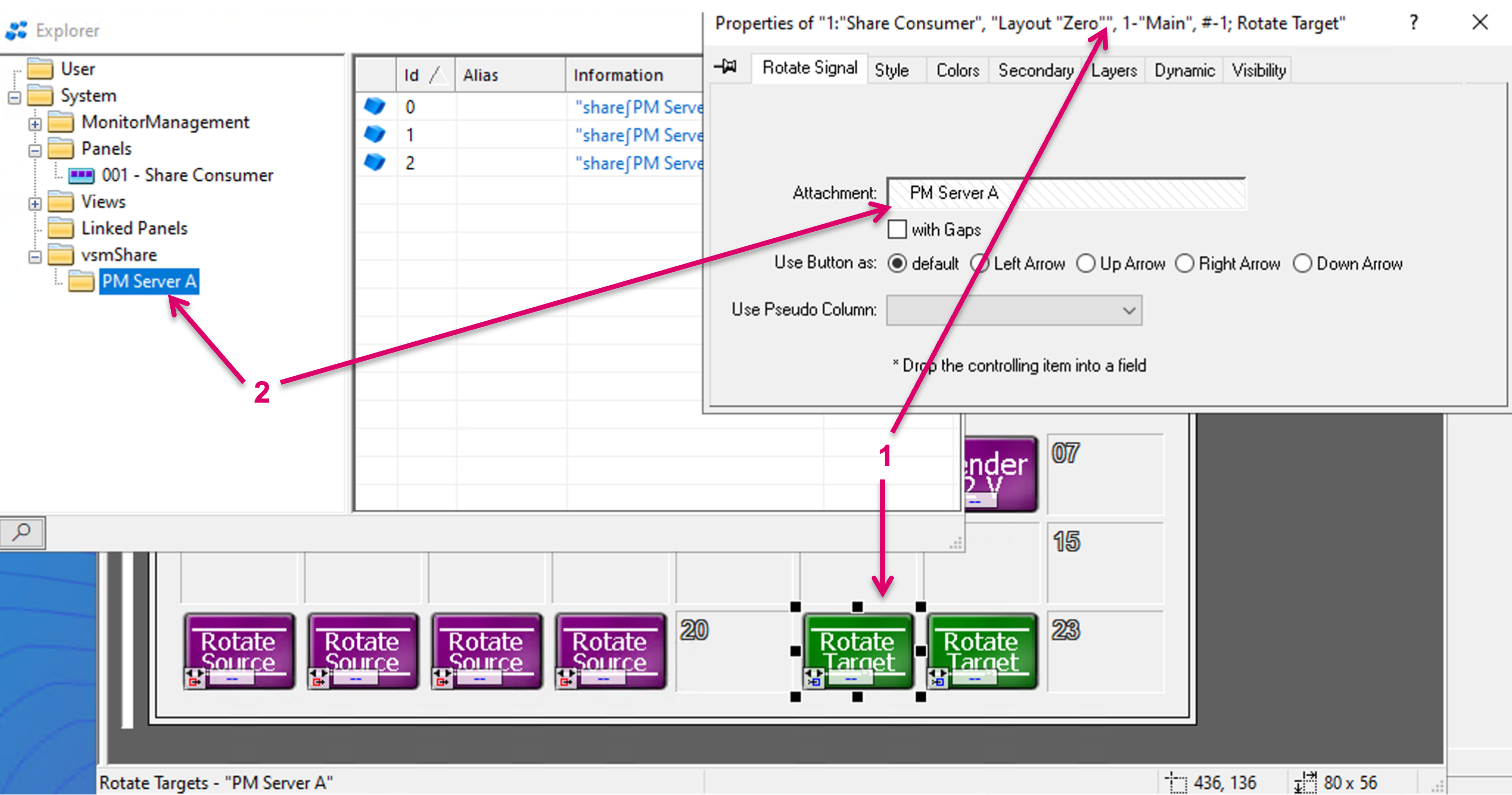
To add shared Targets to the panel, add multiple Rotate Target buttons to the Panel Page. Select the first Rotate Target button and in the button Properties window (1), navigate to tab Rotate Signal. Then drag and drop the vsmShare/Remote System folder node from the Explorer view into the attachment area of the button properties (2).
- The workflow of operating and routing the same Target on Provider and Consumer side in parallel is not recommended.
- A shared target is still owned by the Provider and can potentially still be routed on the Provider side. Such local route on the Provider side is not indicated on the Consumer and operators may face a false crosspoint status.
- While a Consumer system can drop the usage of a shared Target by assigning its local Blind Source, this will not result in an effective Blind route on the actual Target. This may lead to inconsistent routing status display where the Provider may see the (effective) local source routed to its own Target while the Consumer would see his local Blind as Source for the same Target. Only the Provider can Blind its own Targets.
Send Source Tally to Provider
Optional the Consumer can send Tally states for shared Sources to the Provider. To enable this option, navigate to Matrix Properties (1) and to submenu Server Management (2). Make a right-mouse-click on the Zone ID of the respective Remote side (3), that is sharing resources and shall receive Tally states. In the pop-up menu, select Configure Tally Mapping (4).
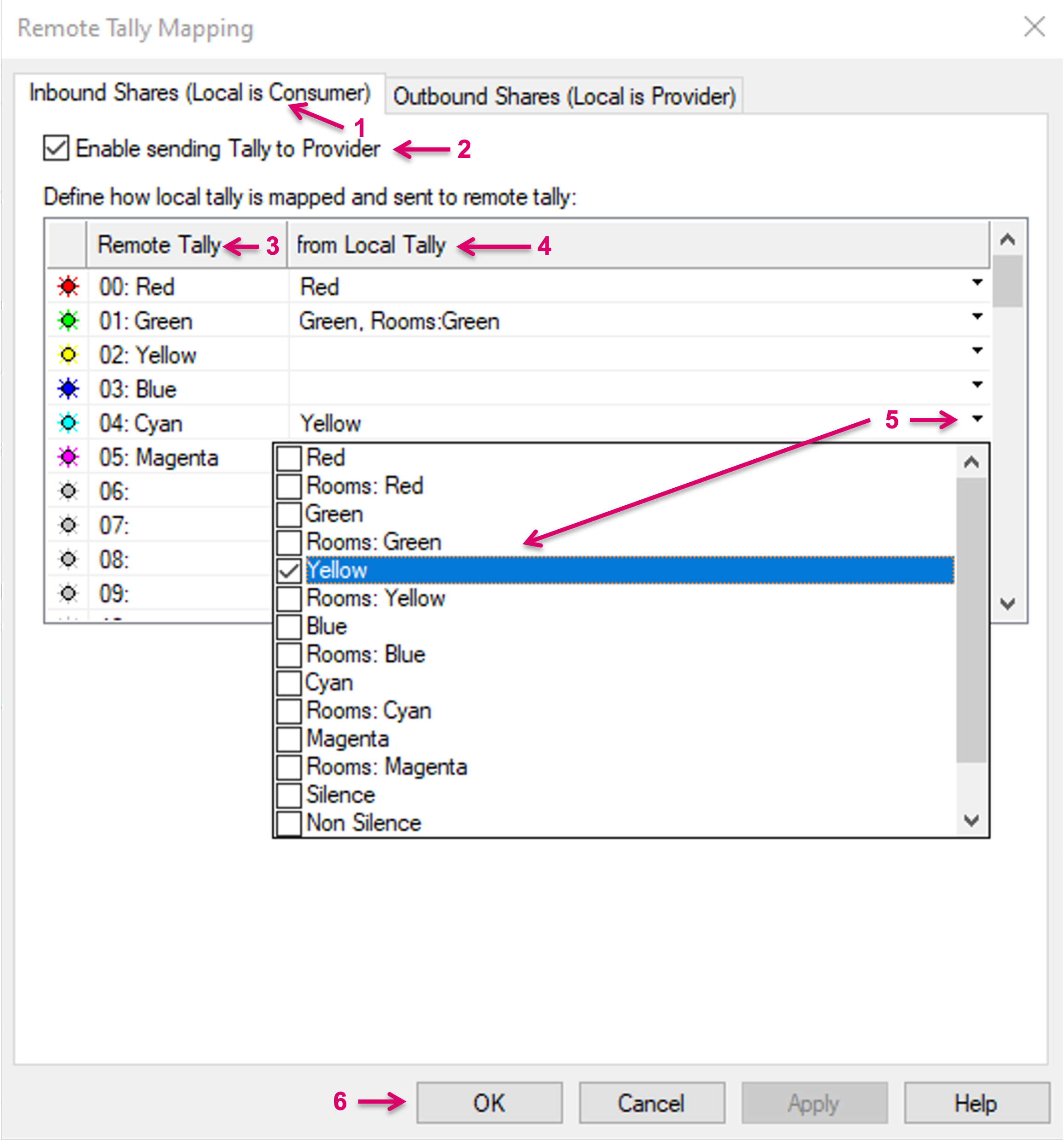
In the opening Dialogue navigate to tab Inbound Shares (Local is Consumer) (1). Check the option Enable sending Tally to Provider (2). The table below allows to map the local system Tally levels to the Tally sender. The column “Remote Tally” (3) lists all labeled Tally levels which can be sent via vsmShare. The column “from Local Tally” (4) allows to map the local Tally levels that shall be sent. By click on the small arrow in any of the “from Local Tally” cells, it can be selected which local Tally shall be sent as which Tally level/color to the Remote/Provider system (5). An n:1 assignment is possible. Finish the configuration with OK (6).