vsmStudio - Room Tally

Introduction
The Room (-Tally) feature in vsmStudio allows workflow specific mapping between System Tally and Production related Tally levels. The use of this feature may be applicable or even essential if one VSM system must manage multiple control rooms or sites, where each of these separate Production suites have their own specific Tally requirements. Room Tally configuration can be acessed via Explorer Directory or Monitor Management.
The Room concept
A Room represents e.g., a logical Production environment within a broadcast system, for instance a Control Room Gallery. Once a Room is created it allows to group the relevant Signal Path resources within one collection. Based on this a Tally mapping allows to “translate” Tally levels, and effectively Tally colors, between different Rooms. This enables for instance the possibility to have a Red Tally of one Control Room being displayed as Yellow Tally in another Control Room and vice versa.
About System Tally
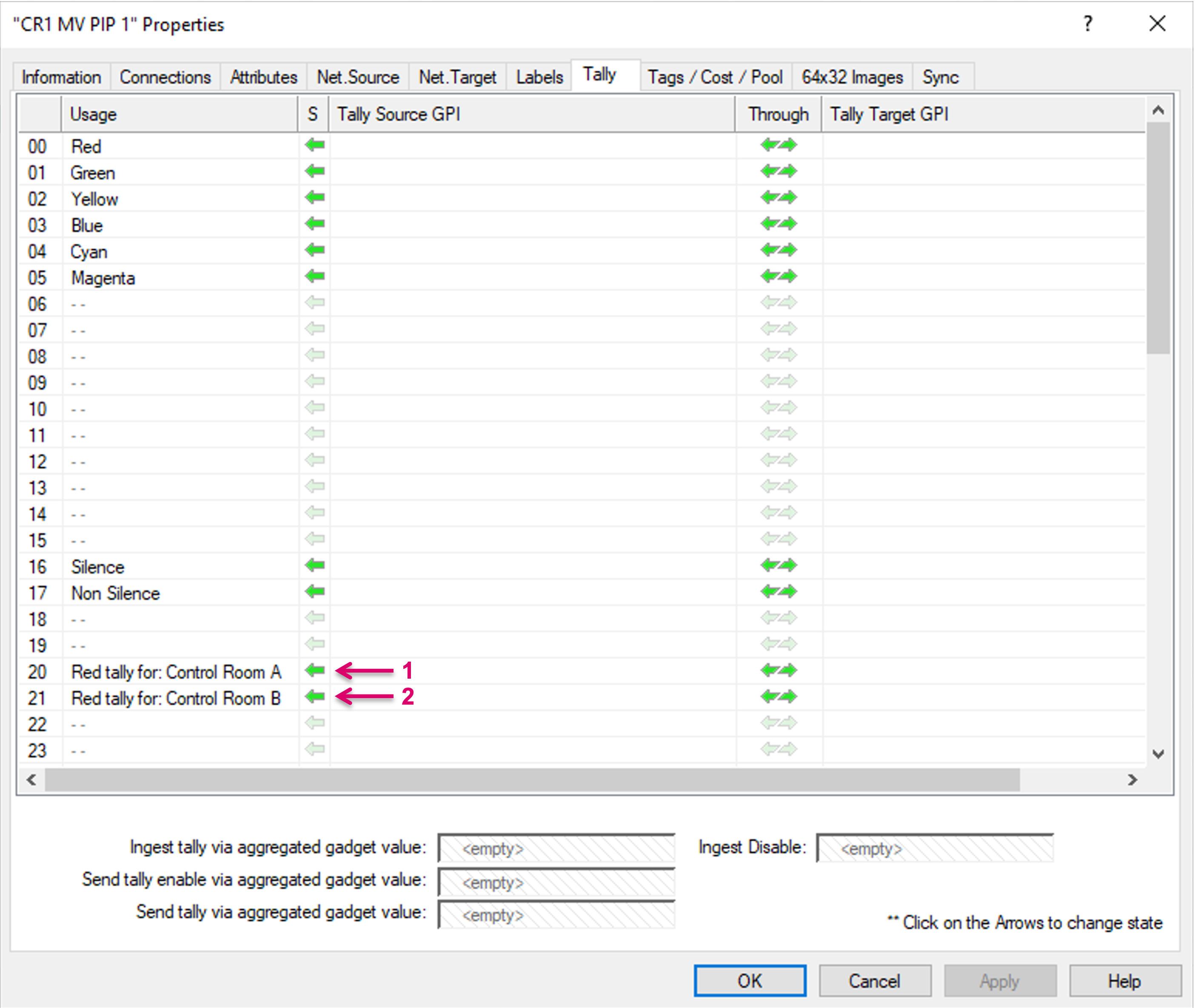
vsmStudio comes with 64 System Tally levels. These levels are accessible via the Signal Path Properties (1) Tally tab (2). Every Signal Path can be in and carry any of these 64 independent Tally states. The usage of some specific System Tally levels is predefined by default (4) as they may be also tied to protocol specific data transfer. e.g., the usual On Air Tallies: Layer 00=Red, 01=Green and 02=Yellow (4). Other levels may be freely used for various usage.
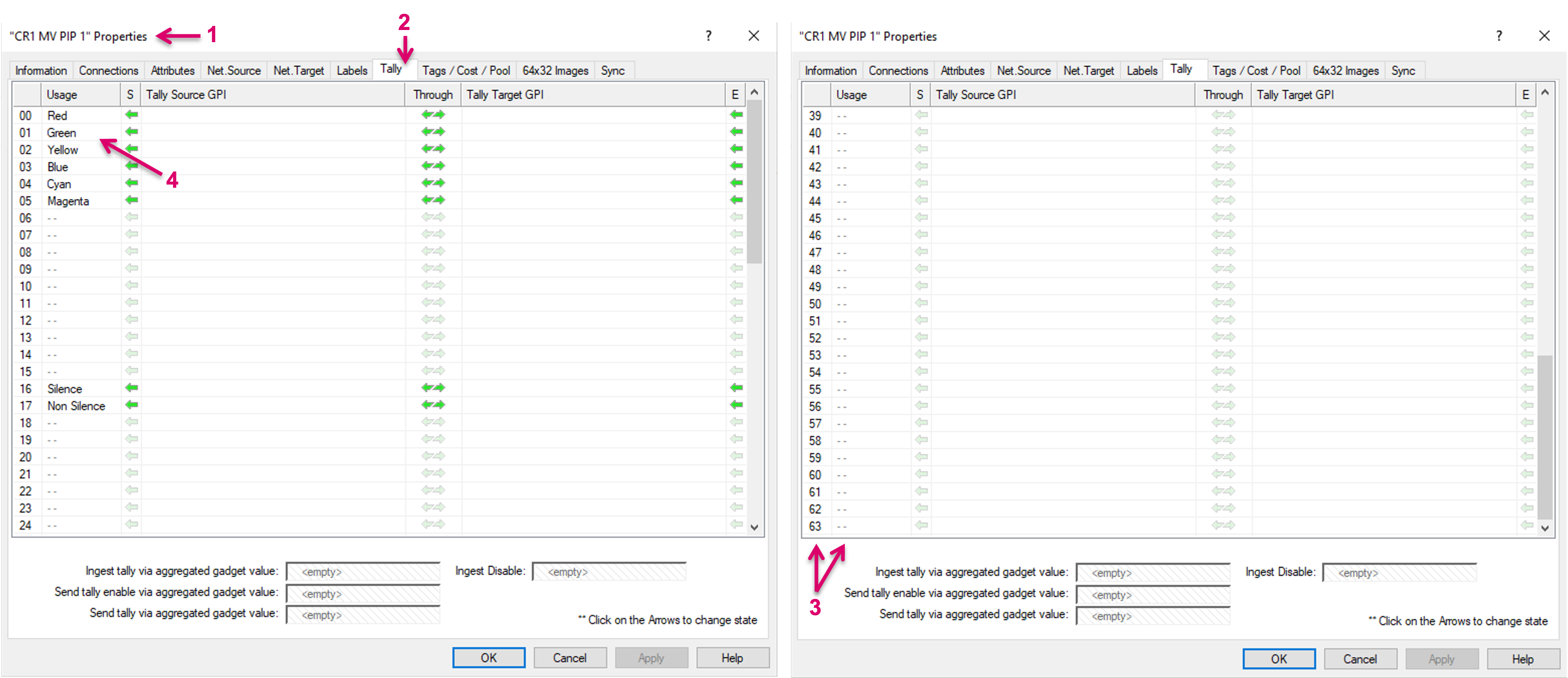
While one, system-wide Red Tally may not be sufficient to serve multiple Production Suites with different requirements, the Room Tally feature was introduced to allow a flexible mapping.
Creating Rooms
The configuration can be accessed via Explorer Directory or Monitor Management. This documentation is focussing on the Explorer view.
Navigate to the Explorer view via the respective Icon on the main menu bar.

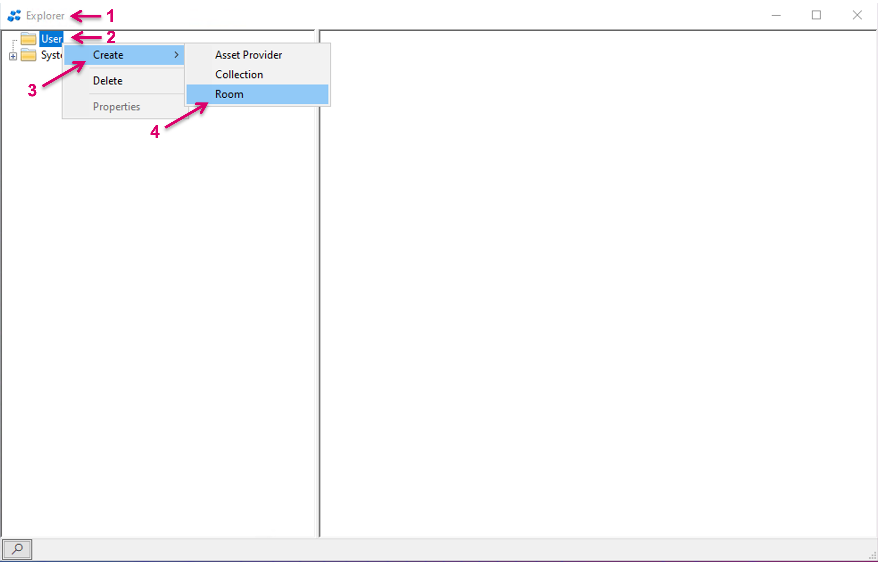
In the Explorer view (1), right-mouse-click on User (2), then select Create (3) and Room (4).
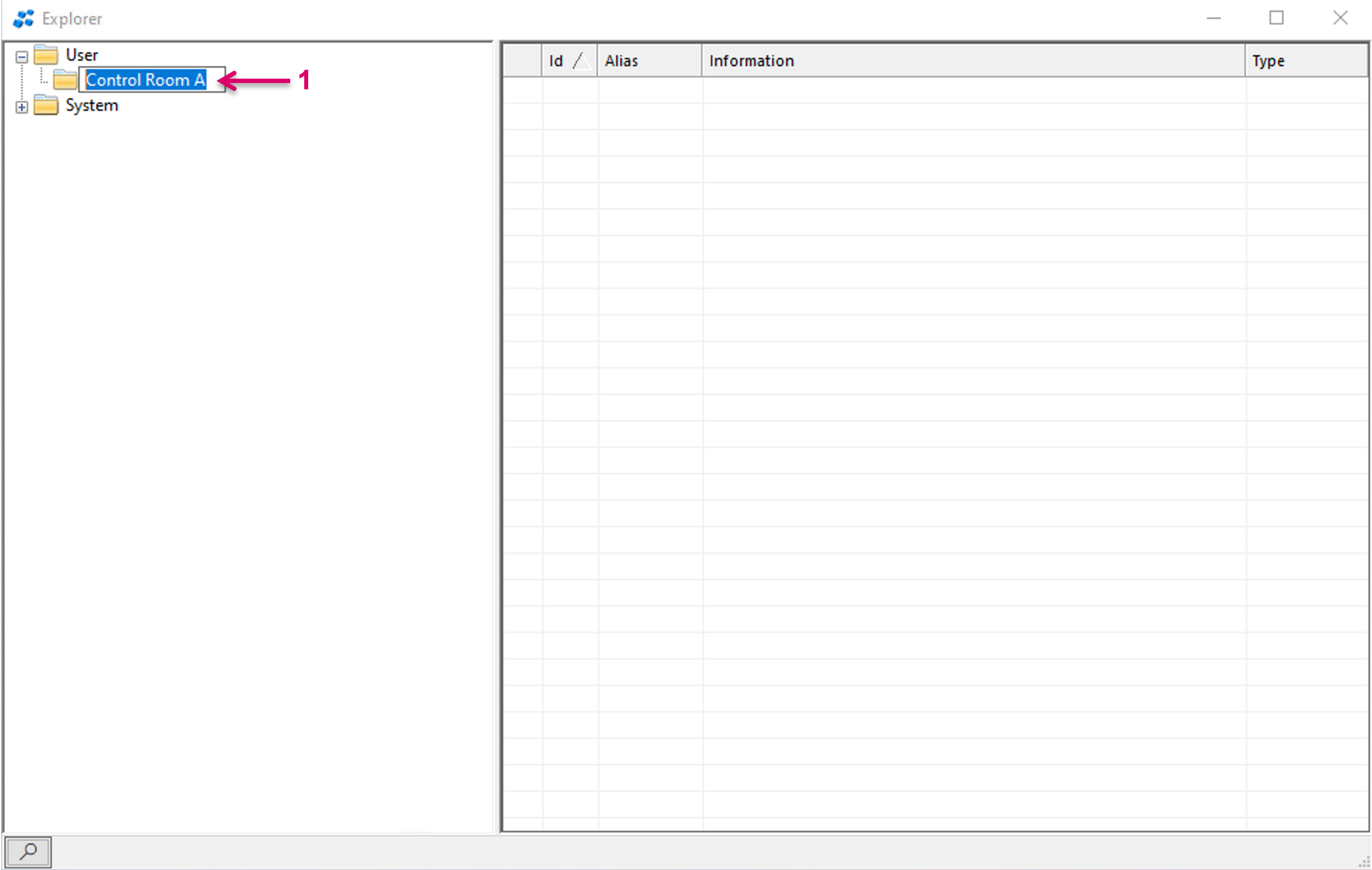
Assign a descriptive name for the created Room (1), e.g. Control Room.
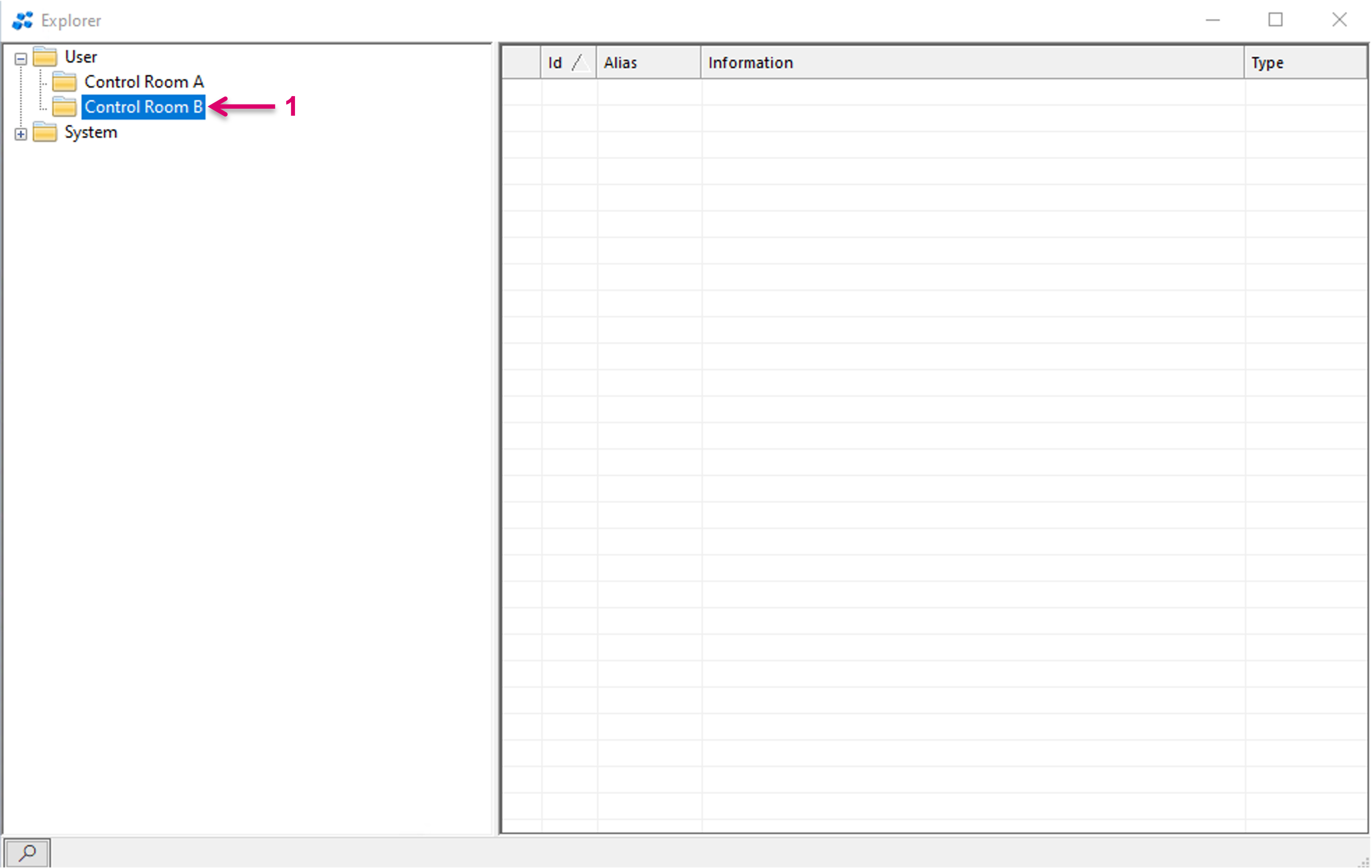
Repeat these steps to create multiple Rooms (1).
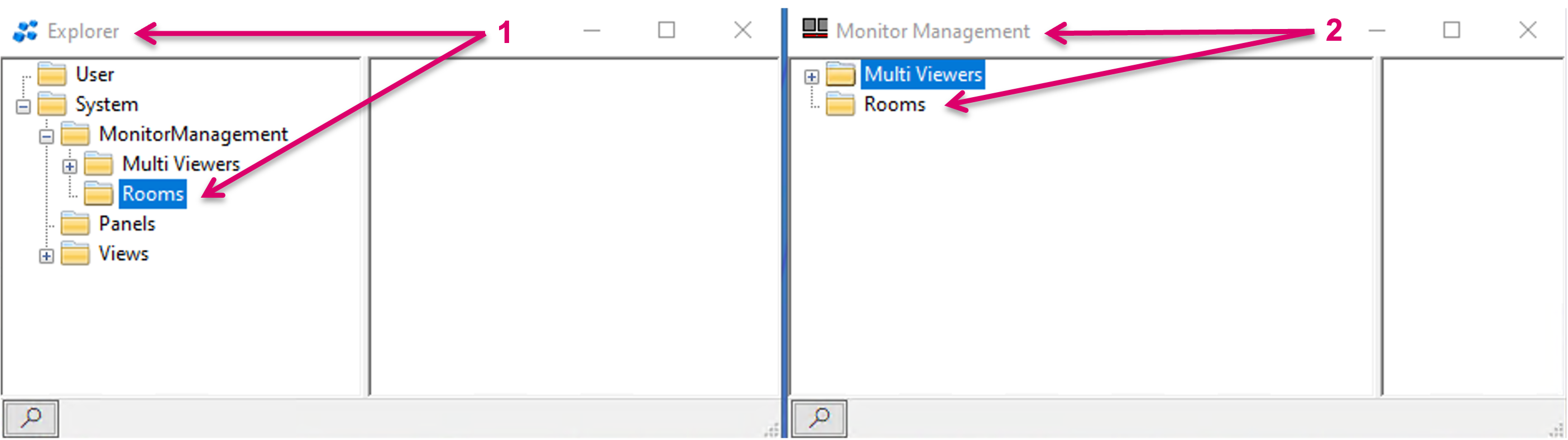
There are multiple access points for Rooms that are effectively all leading to the same configuration screen. While this documentation is based on access via Explorer view and the User node, possible alternative access points are via Explorer tree System node/MonitorManagegement/Rooms (1) or via Monitor Management window/Rooms (2).
Assign resources to Rooms
Next step is to assign respective resources, in form of Signal Paths, to a Room. This is done via drag and drop, either from Signal Path list or Matrix view (1). Select one or multiple Target Signal Paths, in this case Multi-Viewer PIP Targets (2).

Then drag and drop them onto the folder symbol of the respective Room (1). Right after, the assigned resources will be listed accordingly in the right-hand area of the window (2).

Room Tally mapping
To proceed with the Tally mapping for a Room, enter the Room Properties. Access the Properties via double-click on the respective Room folder or right-mouse-click on the folder and select Properties (1).

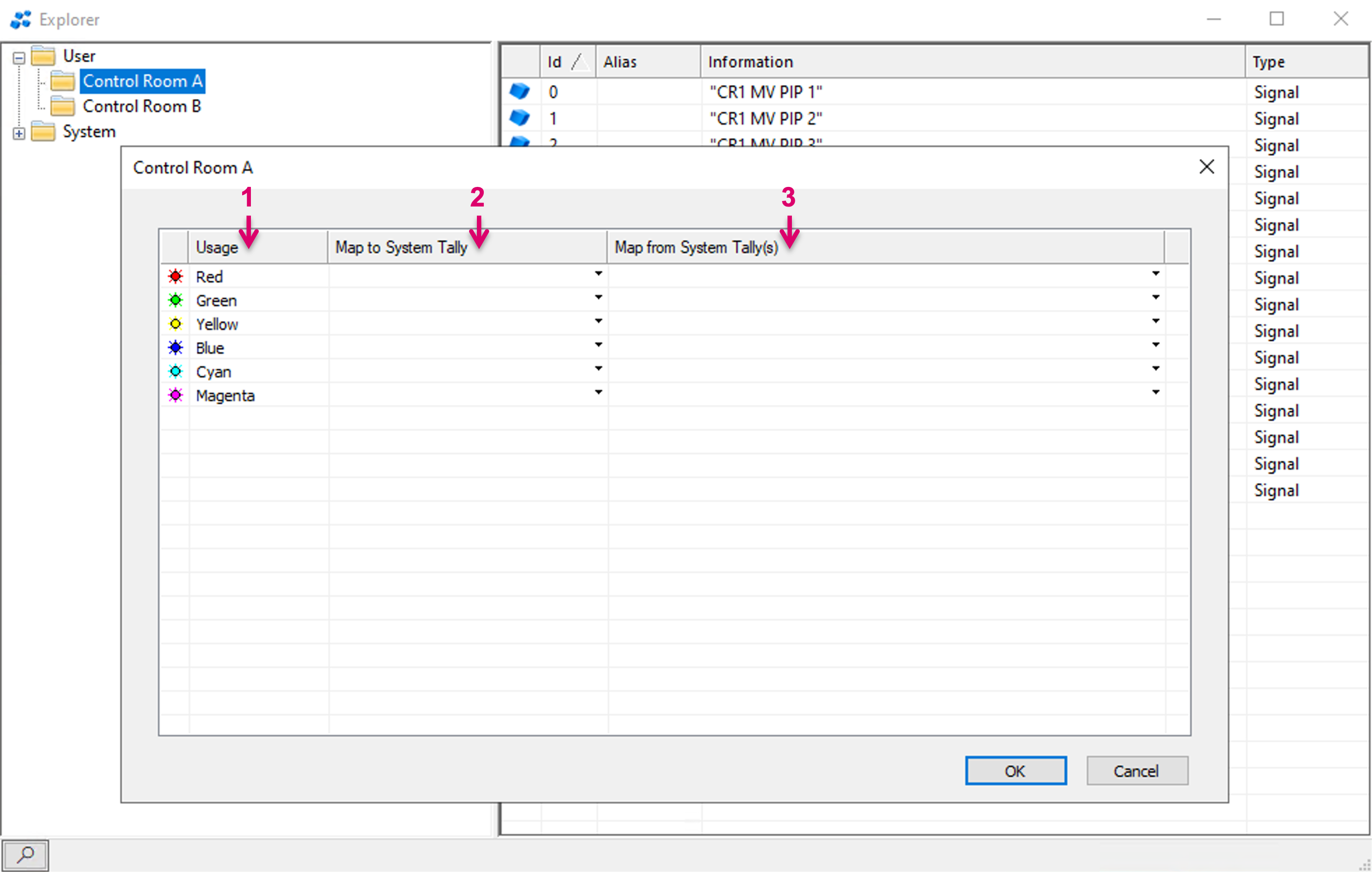
The Properties and Tally mapping view shows multiple columns.
- Usage: Represents the local Room Tally (1).
- Map to System Tally: Allows to select any of the 64 System Tally levels to be a local Tally for this Room (2).
- Map from System Tally(s): Allows to select one or multiple System Tallys to be mapped to a specific local Room Tally (3).
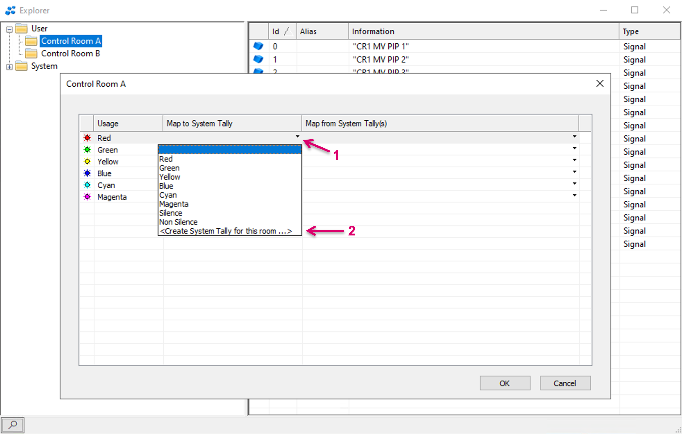
To choose any of the 64 System Tally levels to be an exclusive local Tally for this Room, click on the little arrow in a cell of the respective row (1). Select the respective System Tally from the drop-down menu. Aside the possibility to choose from any of the listed (already labeled) System Tally levels, the dialogue offers to choose another, potentially free System Tally level, by clicking “<Create System Tally for the room…>” (2).
If selecting “<Create System Tally for the room…>”, a pop-up window will show up, which allows to select any of the free/unlabeled System Tally Levels/IDs. A free one will already be suggested and show (1). If desired, a different, descriptive name can be entered (2).

The newly named Tally Levels will show accordingly on the Tally tab in System Path properties (1)(2).
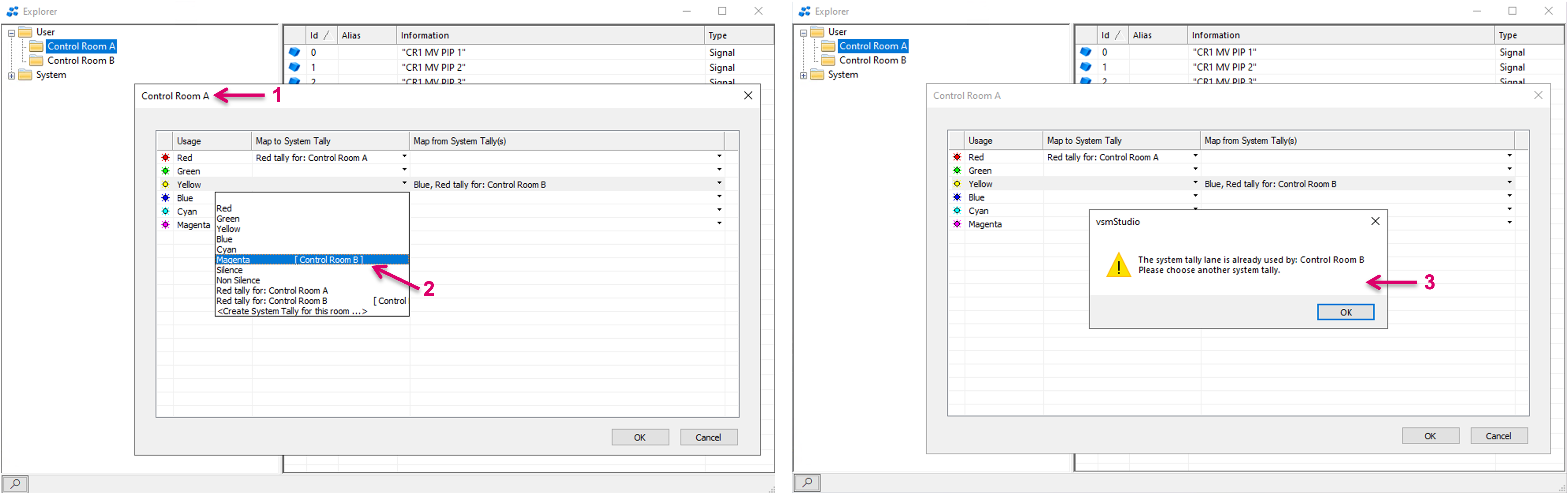
Only one System Tally can be mapped to a local Room Tally and the mapping is exclusive. In the example with “Control Room B” below (1), we see System Tally level “Magenta” being assigned to Room Tally level “Blue” (3).

If now another Room, e.g., “Control Room A” (1) opens the drop-down menu to map a System Tally, it is clearly displayed that “Magenta” is already assigned to “Control Room B” (2). If selected anyways, a notification will pop-up accordingly (3) and the assignment will not be executed.
The column “Map from System Tally(s)” allows to select one or multiple System Tallys to be mapped to a specific local Room Tally and effectively to be displayed in the respective Room Tally level/color.
In the following example the Properties view of “Control Room B” is opened (1). By click on the little arrow in a cell of the respective row (2), any of the 64 System Tally levels can be selected from the drop-down menu (3).

Room Tally result and monitoring
Please note that the result of the Room Tally mapping will not be displayed and visible in the Primary Virtual Matrix view or any pLayer matrix view. The effective result will primarily be visible via attached UMDs or on external Tally or Multi-viewer systems, where the effective Room Tally will be sent to.
To test the configured Tally mapping, the Room Tally dialogue provides the option to open a dedicated view per Room.
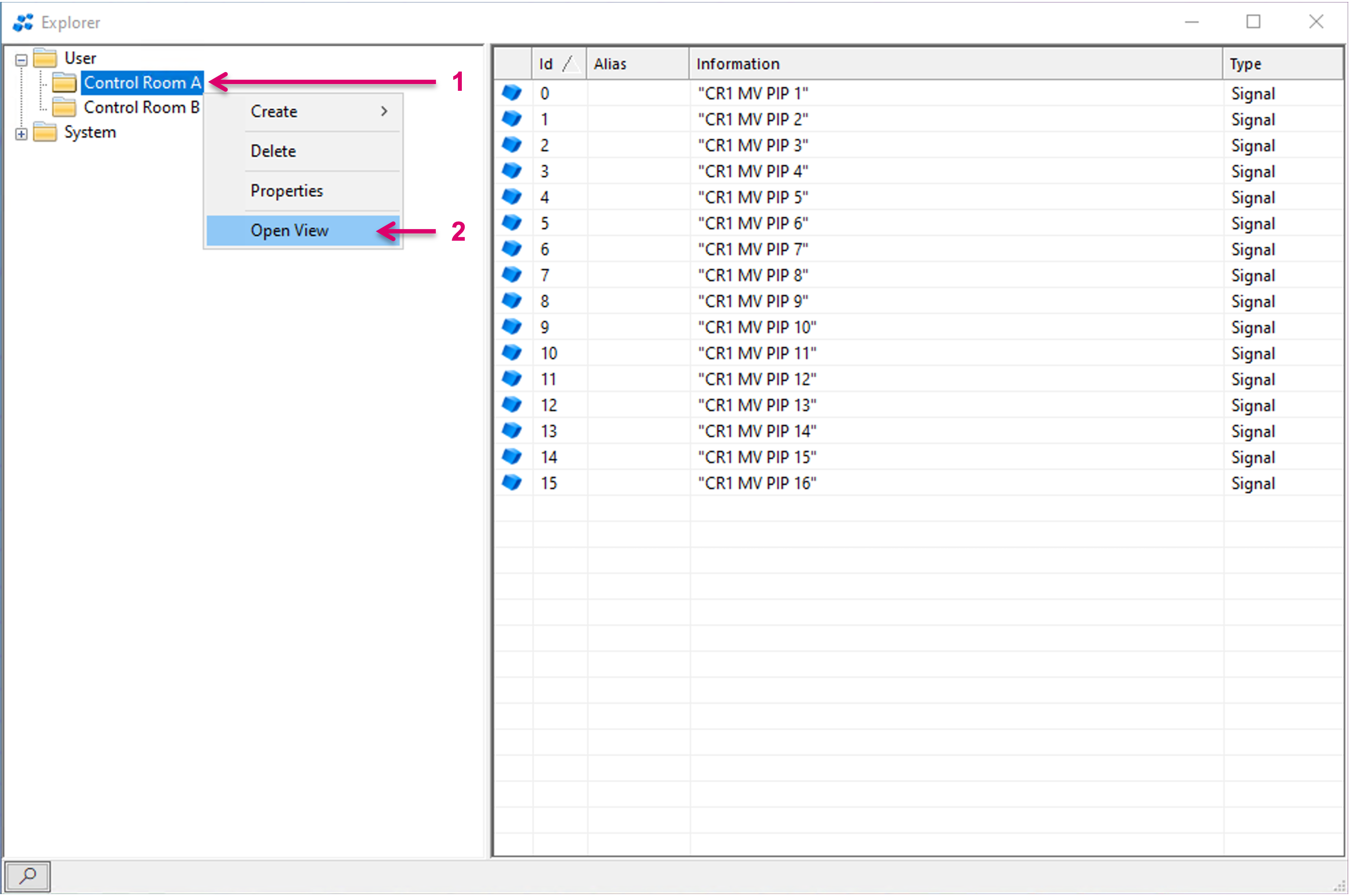
Right-mouse-click on a Room folder (1) and select “Open View” (2).
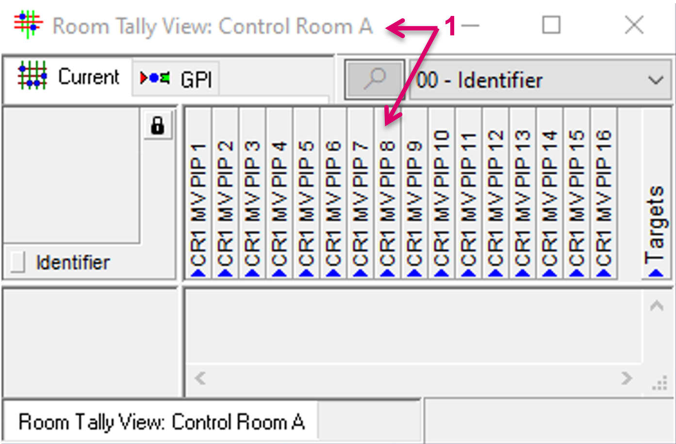
A Room specific view window, including the assigned resources will open accordingly (1).
Multiple views can be opened in parallel. The picture below shows a pLayer matrix view (1), side by side with two Room views (2). The pLayer view shows the different System Tally assigned to Control Room specific Switcher Targets (3) (4). The System Tally assigned to these targets is not enabled yet, hence the Sources do not receive any Tally and no Tally state is shown in the Room views.

Once the respective System Tallys are enabled, the Sources assigned to the Control Room Switcher Targets (1) (2) get Tally (3). The Source Tally is then also inherited to the Multi-viewer PIPs, to which the respective Sources are routed. In the pLayer matrix view the System Tally shows on the Multi-viewer Targets (4). The Room views show the effective result of the Room Tally mapping.
- Cam 1 is on Air and receives Red Tally in Control Room A but shows Yellow in Control Room B.
- Cam 3 is on Air and receives Red Tally in Control Room B but shows Yellow in Control Room B.
