RPS - Installation Guide
The RPS is a UL and CE certified external stand-alone device offering a redundant power supply solution for Lawo Radio console frames and A__line devices. It contains two independent, equal power circuits, path A and B, and an status-GPO per path for external indication.
Both paths A and B provide two Kycon input connectors and status indications on the front panel and two output connectors plus an independent GPO per path on the rear panel.
The failover happens automatically and does not require any configuration.
| PSU Type | Type Number | Article Number | |
|---|---|---|---|
| 12V DC Redundant Power Switch | 712/10 | 271-2100-000 | |
Ordering Information
To order a spare part, please use the part numbers listed above.
Specifications
For dimensions, weight and electrical specifications, please refer to the data sheets for the Redundant Power Switch. These are available from the Lawo Download-Center (after login).
The RPS permits two types of External Desktop PSUs:
| Name | Article Number | Description | |
|---|---|---|---|
| Small PSU | 485-1209-000 | 12 VDC / 3,3 ADC | |
| Large PSU | 485-1211-000 | 12 VDC / 7 ADC | |
It is mandatory to connect two PSUs of the same type to one path, but it is possible to use different type-pairs of PSUs for each of the two paths within the RPS.
The RPS does not contain any fan and is therewith silent, so it can be placed close to the supplied device.
Related Products
| Product | needed PSU Type | |
|---|---|---|
| new crystal | 12 VDC / 3,3 ADC | |
| diamond | 12 VDC / 7 ADC | |
| VX modules | 12 VDC / 3,3 ADC | |
| A__mic8 | 12 VDC / 3,3 ADC | |
| A__digital8 | 12 VDC / 3,3 ADC | |
| A__OnAir4 | 12 VDC / 3,3 ADC | |
Using the RPS
The In- and Output connectors are based on the Kycon connector. The input is a 4-pin connector, and the output is a 3-pin connector to avoid connections in the wrong direction. For the output connections, two Kycon 3-pin to Kycon 4-pin cables are supplied with every Redundant Power Switch. Additional cables can be ordered separately.
Connecting the DC Input
- Start by connecting the External Desktop PSUs to the DC inputs on the front panel using the 4-pin Kycon-connectors.
- Then, using the IEC cables provided, connect your mains supplies to the External Desktop PSUs.
Connecting the DC Output
- Connect the DC outputs(s) on the rear panel of the RPS to the DC input of the desired HW using the 3-pin Kycon-connector and the cables supplied.
Using RPS for Redundancy
Using the RPS as a redundant power supply unit offers the following setup scenarios per RPS.
for diamond
The example below shows a single diamond console 2ME with virtual extension.
- 1x diamond frame with 2 modules including its Virtual Extension (2x 7 ADC for the console; 2x 3,3 ADC for the VX screen).
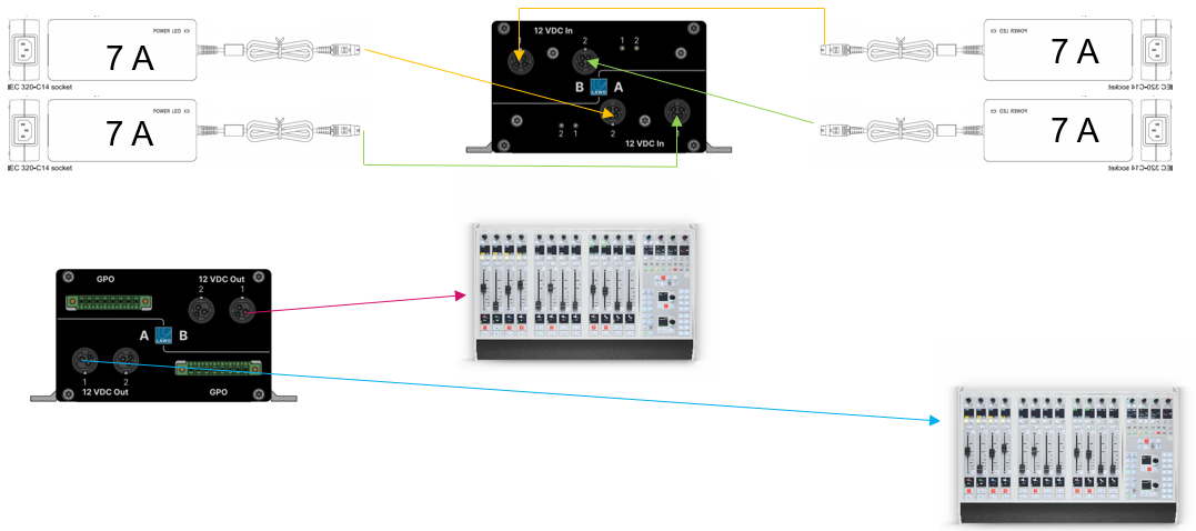
The next example shows two diamond consoles 4 ME without virtual extension.
- Two separate diamond frames without Virtual Extensions and a maximum of 4 modules including Key- and Rotary-Extension modules each. (2x 7 ADC per console).
for new crystal
The example below shows a single new crystal console with virtual extension.
- 1x new crystal-frame (2 modules) including the Virtual Extension. (2x 3,3 ADC for the console; 2x 3,3 ADC for the VX screen).
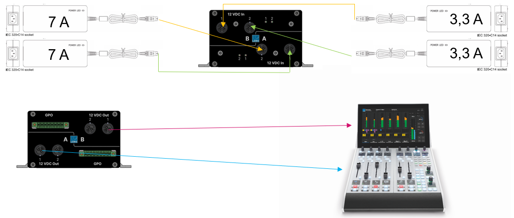
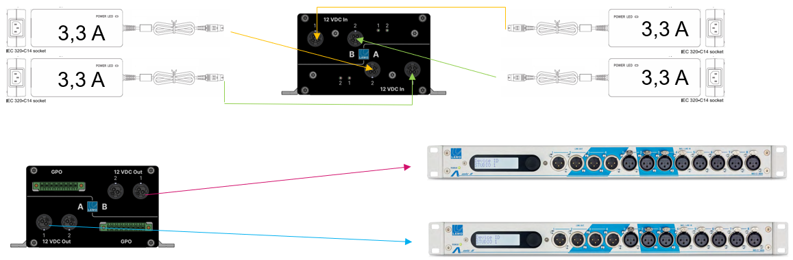
for A__line devices
The example below shows two A__mic8 devices.
- 2x A__mic8 using one of the paths A or B for each device (2x 3,3 ADC for device A; 2x 3,3 ADC for device B).
Using the RPS to reduce the number of PSUs
The RPS can also be used to reduce the number of power supply units located close to the console. In this instance, the following scenarios can be achieved per RPS:
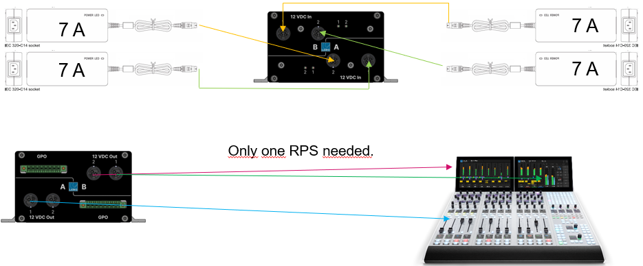
for diamond
The example below shows a single diamond console 4 ME with virtual extension.
- 1x diamond frame with 4 modules including Key- and Rotary-Extension modules and two Virtual Extension screens. (2x 7 ADC redundant for the console; 2x 7 ADC for the Virtual Extensions without redundancy).
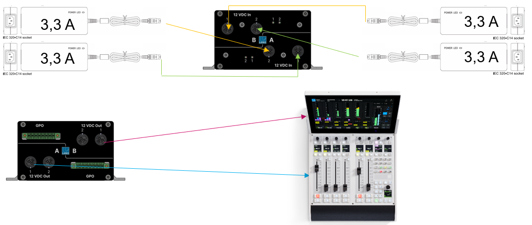
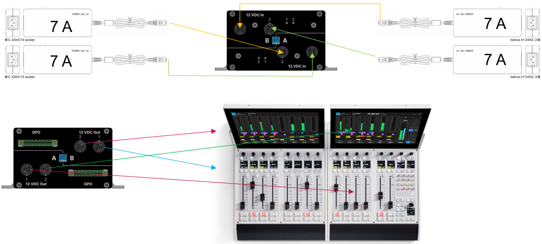
for new crystal
The next example shows a single new crystal console with virtual extension.
- 1x new crystal console with two frames (4 modules) including their Virtual Extensions (2x 7 ADC for the console; 2x 7 ADC for the VX screens).
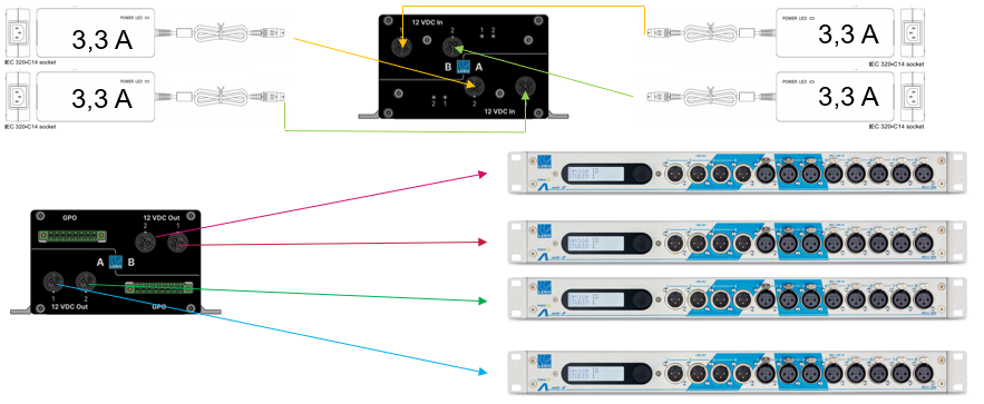
for A__line devices
The example below shows four A__mic8 devices.
- 4x A__mic8 powered by one RPS (2x 3,3 ADC for two devices connected to path A; 2x 3,3 ADC for two devices connected to path B).
Using the GPOs
The two GPOs for path A and B can be used to indicate the RPS's redundancy state within the console or Virtual Extension by connecting them to the Power Core's GPIs and configure the desired indication via On Air Designer. Please reach out to the PSG Team for further guidance.
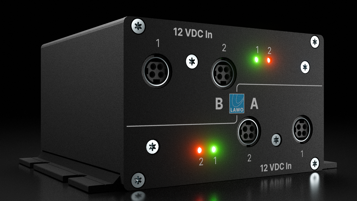
Status LEDs
The status LEDs "1" and "2" (at the front of the frame) light once power is applied. The color-coding of the LED is described below.
| CONTROL Port LED | Meaning |
|---|---|
| Off | the corresponding input is not connected or powered. |
| Red | the corresponding input is connected and in passive mode. |
| Green | the corresponding input is connected and active. |