diamond - Mounting the VX Modules
If the Virtual Extension is included, then each VX module is shipped separately. The VX modules must be mounted into the frame, once the frame is installed. All VX modules are identical and so they can be mounted in any order.
Overview
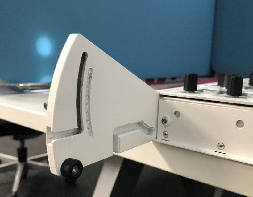
The VX frame comes with special side profiles that hold each VX module. The profiles include two pre-drilled channels into which the module slides. On the rear of each VX module are two fastening screws and two spring-loaded bolts that secure the module to the frame: one screw and bolt for each side.
Once the VX module is installed, the viewing angle can be adjusted to one of three positions by loosening the two fastening screws and gently tilting the display. This allows users to change the viewing angle to suit their own personal preference. Click here to see how the user adjustment of the viewing angle should work.
Mounting Instructions
1. On the rear of the VX frame, remove the two black circular stands from the end of the side profiles.
There are two stands to remove: one on the left and one on the right. The image below shows the left side.
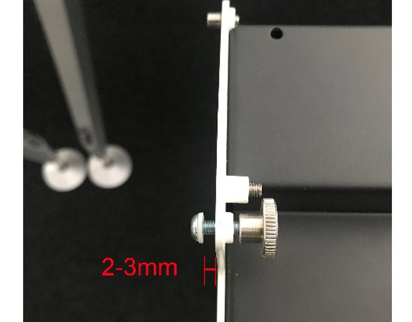
2. At the bottom of the VX module, loosen the fastening screws by turning the knurled-head end until the distance is about 2-3mm.
There are two screws to loosen: one on the left and one on the right. The image below shows the left side.
3. Lift the VX module and fit the first liner, from bottom to top, into the inner channel on one of the side profiles. Then repeat for the other side.
The image below shows the left side.
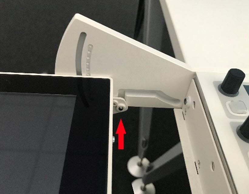
4. Raise the VX module slightly and push the second liner, from the back, into the outer channel on one of the side profiles. Then repeat for the other side.
The image below shows the right side.
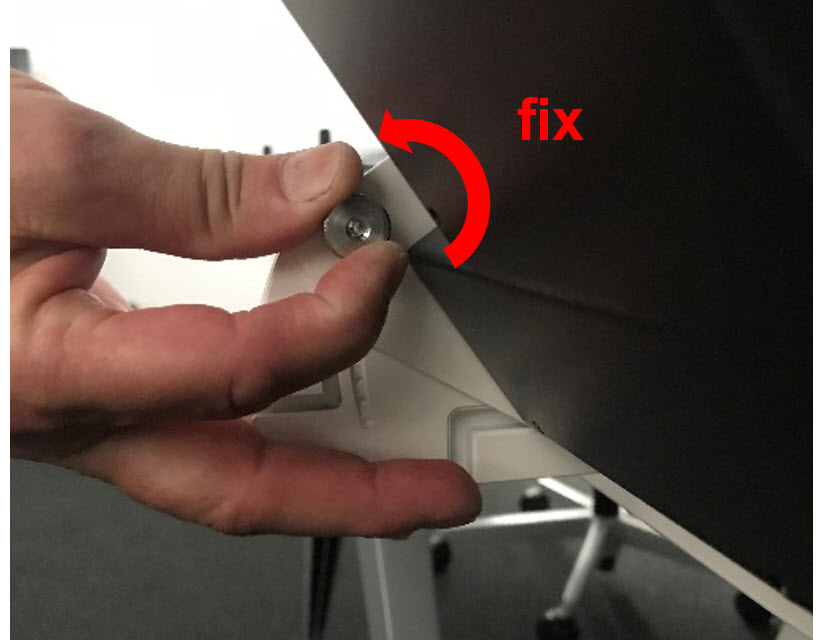
5. Raise the VX module so that it slides fully into the two channels, and clamp by turning the knurled-head screws in a left-hand /anticlockwise direction.
There are two screws to clamp: one on the left and one on the right. The image below shows how to clamp the left side.
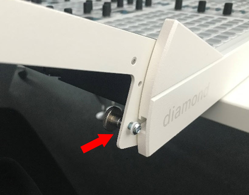
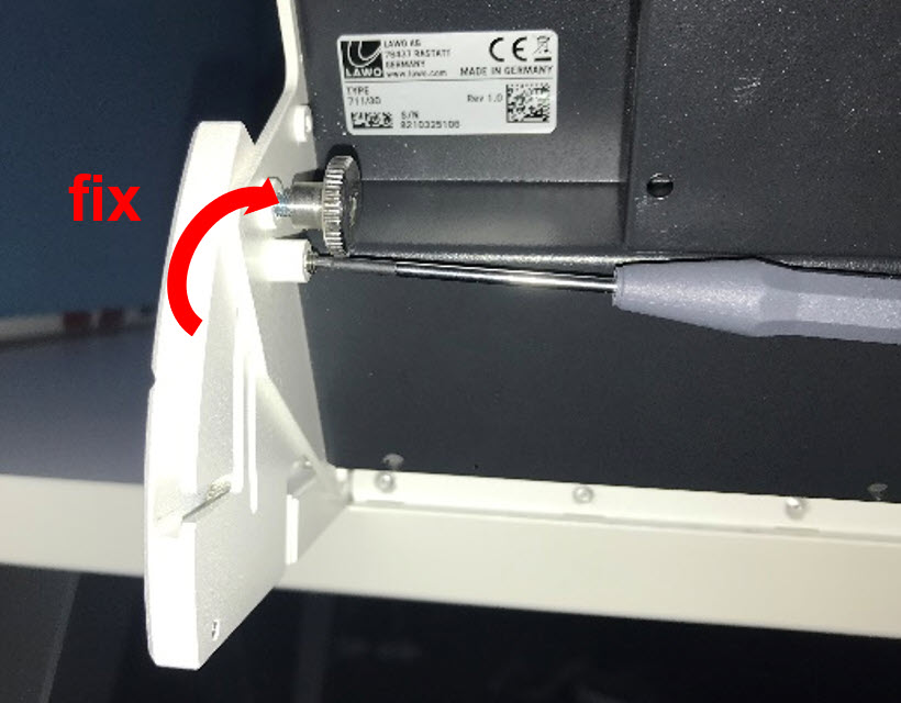
6. Secure the VX module to the frame by tightening the spring-loaded bolts using an Allen 2.0 screwdriver. You should tighten until the bolt is flush with the side plate. Do not overtighten or use excessive force.
There are two bolts to tighten: one on the left and one on the right. The image below shows how to tighten the left side.
7. Replace the two black circular stands (removed in step one). Once in place, the stands act as feet to support the rear of the frame and prevent any downward movement of the VX module.
8. Check the movement of the VX module when the viewing angle is adjusted, and adjust the spring-loaded bolts and knurled-head screws if necessary.
Full instructions for the user adjustment of the viewing angle can be found here.
Fitting the Cable Cover
Optionally, a cable cover can be fitted to protect the connections and make the rear of the console look nicer. The cable cover is not included and must be ordered separately.
The cable cover should be fitted once the VX module is connected and the system is fully tested.
There are four plastic pins that hold the cover in place. The image below shows the rear of a VX module with the cable cover fitted.
")