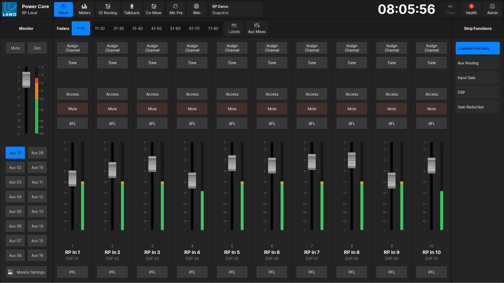
VisTool RP - Mixer
The Mixer page provides on-screen control of the Power Core RP v2 DSP channels.
Structure
The Mixer page is divided into four sections:
- Mixer Functions Top Bar - Used to switch between fader banks, edit user labels, or enter Aux Mixes mode
- Monitor Side Bar - Used to control the local monitor bus
- Strip Functions Side Bar - Used to switch the mini-displays at the top of each fader strip
- Fader Strips - 10 Fader strips
Mixer Functions Top Bar
The Power Core RP contains 80 faders, to which each of the 64 DSP Inputs and 16 Aux Buses can be mapped. The faders are arranged in banks of 10, and both the Local and Remote user can switch between fader banks independently of each other.
Monitor Side Bar
The Monitor Side Bar provides control over the users (Local or Remote depending on the session configuration) monitor bus.
The Mute and Dim keys can be used to mute or dim the monitor output.
The fader can be used to control the overall level of the monitor bus (a pre-level control Monitor Bus output is also available). The PPM Meter will show the pre-level control signal level of the monitor bus, after any AFL/PFL inserts.
Press one of the AUX xx buttons to monitor one of the 16 stereo Aux buses. If a user label has been set for an Aux Bus, line 1 of the user label will be displayed instead of AUX xx.
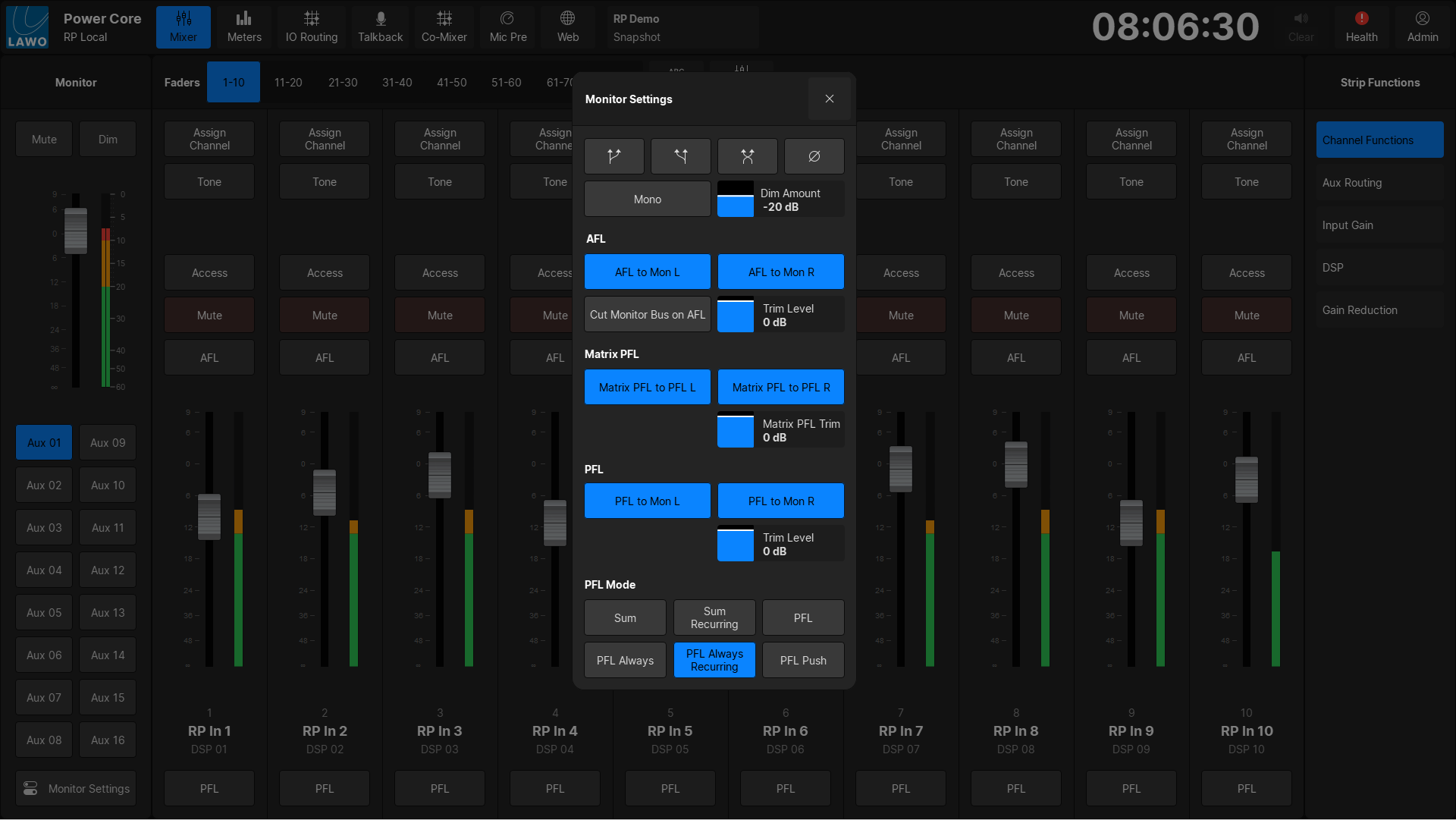
Press the Monitor Settings button to adjust settings such as AFL/PFL insertion behavior, as well as dim levels, PFL modes, and output controls.
Strip Functions Side Bar
The Strip Functions Side Bar is used to switch between mini-displays in the Fader Strips area.
The following functions are available:
- Channel Functions - the default view. Displays the Assign Channel, Tone, AFL, and PFL buttons. For Aux Buses, a Talkback key will also be displayed.
- Aux Routing - displays an overview of the bus routing state for the 16 Aux buses.
- Input Gain - provides a digital gain level control.
- DSP - shows the on/off status of each DSP module: unlit = off, lit = on.
- Gain Reduction - shows meters for the gain reduction applied by the three DSP blocks (Dynamics, Limiter, De-Esser)
Fader Strips
On each fader strip, the following controls are always available:
- Gain - source gain.
- Aux send on/off - for 4 auxes. Use the AUX button (below LAYERS) to page through all 16 aux sends, 4 at a time.
- Access- channel select. Touch to select a channel and open the Access page (described below).
- Fader - channel level.
- Input Meter - channel metering.
- Channel Label - shows the system name (e.g. DSP 01) and the user label (e.g. RP IN 1). The user labels can be edited by clicking the Labels key in the Mixer Functions Top Bar, or from the MC2 console.
- MUTE - channel mute.
If Channel Functions are selected in the Strip Functions Side Bar the following controls are also available:
- Assign- input assign. Touch to assign a processing channel or Aux bus to an on-screen fader. You can choose any of the 64 input channels or 16 Aux buses.
- Tone - inserts a tone generator signal into the Input or Aux Bus. While active the input signal or Aux bus content will be replaced.
- Talkback - (only available on Aux Buses) inserts either the Talkback 1 or Talkback 2 signal into the Aux Bus. Talkback 1 is used for the Local User VisTool session, Talkback 2 is used for the Remote VisTool session.
- AFL - channel AFL (after-fade listen).
- PFL - channel PFL (pre-fade listen).
If Tone is inserted into an Input channel, this will not be reflected on the MC2 RP Input meters!
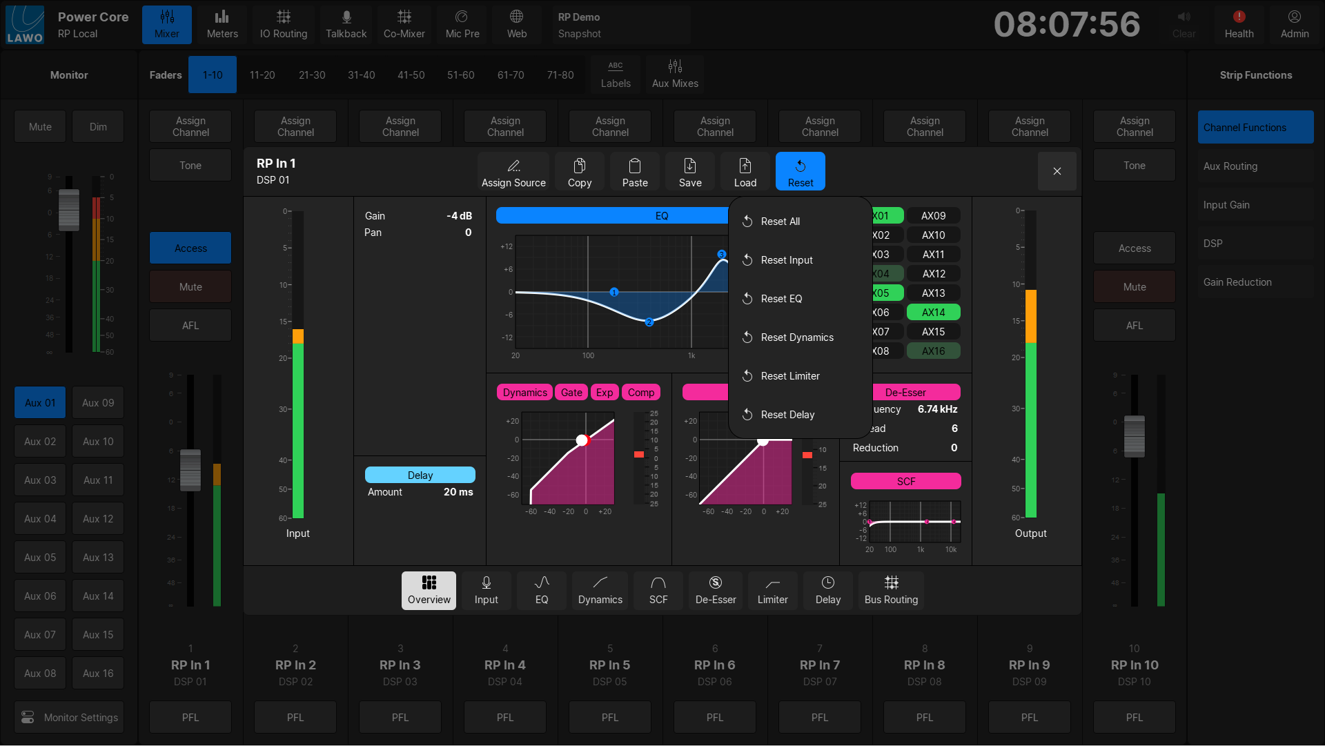
DSP Access
The DSP Access page appears whenever you press a fader strip Access button. It shows all of the available DSP parameters for the selected Power CoreRP DSP channel.
To adjust a switched parameter, such as EQ on/off, touch the button to change its state: unlit = off; lit = on.
For variable parameters, touch and drag anywhere inside the parameter box: dragging to the left will decrease the value, dragging to the right will increase the value.
The Limiter and Dynamics graphs include a red ball which represents the output level. For the Dynamics, this is for the complete Dynamics section: Compressor, Expander and Gate. The ball changes dynamically as the signal level varies, and so is extremely helpful when adjusting parameters.
For convenience, the following operations can be accessed from the top of every page:
- Assign Source - press to open the 'Assign Source' dialog box. From here you can assign a different source to the selected fader strip.
- Copy - press to copy settings from the source in access to the clipboard.
- Paste - press to paste settings from the clipboard to the source in access.
- Save - press to open the 'Save Snapshot' dialog box.
- Load - press to open the 'Load Snapshot' dialog box.
- Reset - press to open the 'DSP Reset' menu, which can be used to reset either all DSP settings, or only the settings for individual modules.
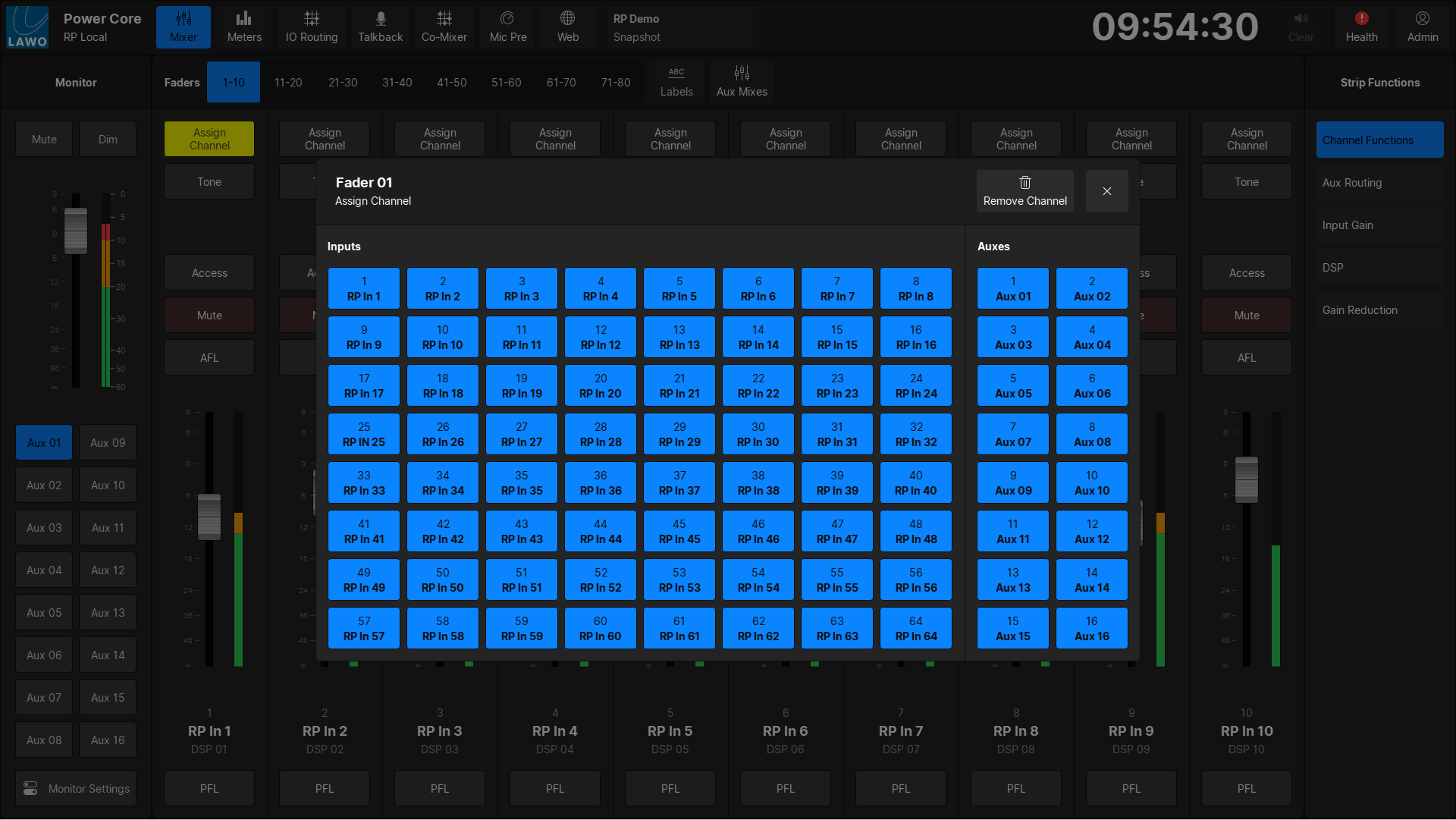
Assign
Any fader strip can control a DSP channel or an Aux Bus. Fader strip assignments are saved and loaded in snapshots.
To assign a channel to a fader, select Channel Functions in the Strip Functions Side Bar then touch the Assign button on the fader strip you wish to assign a channel to. This will open the Assign page.
DSP Channels are displayed on the left half, Aux Buses are displayed on the right half.
Aux Mixes
By pressing the Aux Mixes button in the Mixer Function Top Bar, the Aux Mix mode will be activated, and the contribution level to each Aux Bus can be adjusted.
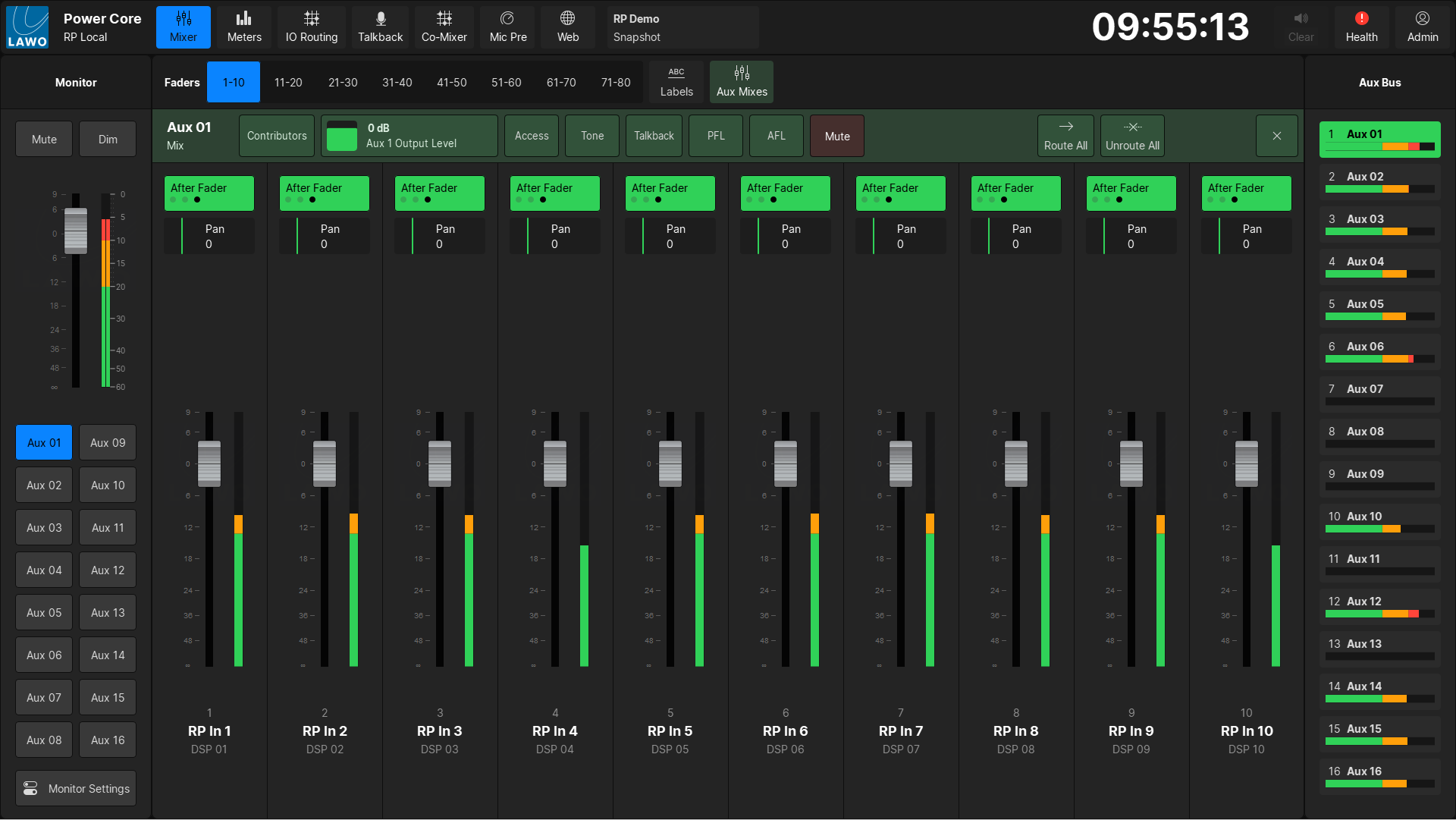
To switch to a different Aux Bus, select the desired Aux Bus in the right hand menu. The selected Aux Bus will be highlighted in green, and the name will be displayed in the Aux Mix Mode Top Bar.
For each Aux Bus, the Top Bar provides the following controls:
- Contributors - This will open the contributors page, which allows user to control reverse aux bus assigns.
- Aux Output Level - This will display the current level of the Aux Master. The level can be adjusted by dragging up or down from within the box.
- Access - This will open the DSP Access page.
- Tone - This will replace the Aux Bus content with the internal tone generator signal.
- Talkback - This will insert either Talkback Input 1 (if the VisTool is configured for the Local user) or Talkback Input 2 (if the VisTool is configured for the Remote user)
- PFL - channel PFL (pre-fader listen)
- AFL - channel AFL (after-fader listen)
- Mute - Mutes the selected Aux Bus
- Route all - Routes all 64 DSP inputs to the selected Aux Bus after fader.
- Unroute all - Unroutes all 64 DSP inputs from the selected Aux Bus.
When Aux Mix mode is activated the Fader Strip Controls will be replaced with a toggle button that can be used to change the bus assign state.
If Aux Panning has been enabled for the selected Aux Bus, then a Pan control will be displayed.