mc²56 - Signal Parameters
The signal parameters editor can be used to adjust settings at a signal level.
The parameters vary depending on the type of signal (mic/line, AES3, etc) and whether you select a source or destination. You can find full details by referring to the I/O data sheets for the remote device. Here we cover the general operation.
Operating Principles
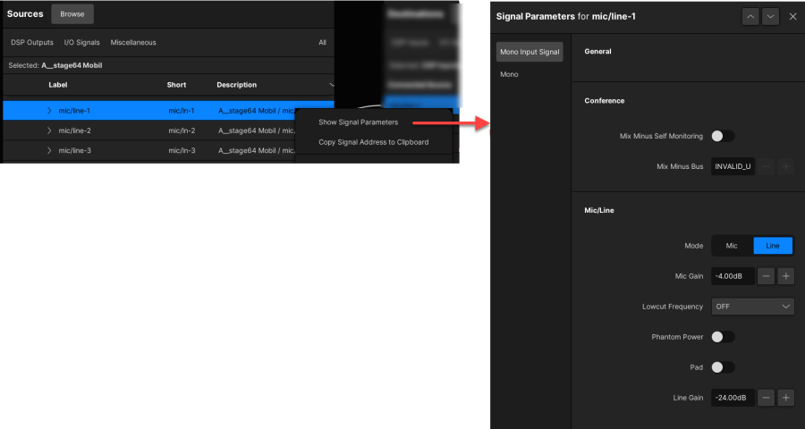
1. Right-click on a signal and select Show Signal Parameters.
The editor can be positioned anywhere on the display by touching and dragging the pop-up window. You can either resize the window or scroll up/down to view all available parameters.
2. Use the tabs on the left to select an individual component (if the signal is stereo or surround).
3. Use the up/down arrows, at the top right of the editor, to scroll through the list of signals without closing the editor.
4. When you have finished editing, select the X to close the editor.
The example below shows the parameters for an A__stage64 mic/line input.

Signal Parameters
The parameters are divided into the following areas.
General
Here you can view and edit the user label fields.
For input channels, the A, B, C source selection buttons provide another way to switch the channel input.
Conference
These parameters appear for input signals and define options for the source's mix minus return.
- Mix minus Self Monitoring - as a default, this parameter is disabled (unchecked). Enable this parameter if you wish to add the selected signal back onto the mix minus feed. For example, if the Talent wants to hear their own microphone.
- Mix Minus Bus - this field provides another way to assign the mix minus bus for the selected source.
Mic/Line
These parameters appear when a mic/line source is selected. They duplicate the mic/line parameters available from the INPUT Control section.
- Mode - selects mic or line level.
- Mic Gain - adjusts the mic/line input gain.
- Low cut Frequency - enables the high pass filter.
- Phantom power - enables 48V phantom power.
- Pad - enables the 20dB pad.
- Line Gain -
AES/EBU
These parameters appear when an AES3 input signal is selected.
Sample Rate Converter On - enables sample rate conversion.
To make a digital path suitable for Dolby E operation, you should disable the Output DSP and any sample rate conversion.
Output DSP
These parameters are available for all types of output signal, and control a small amount of DSP which exists on the I/O card.
- Gain - this field allows you to set an offset level for the selected output signal. It is particularly useful if you are routing a bus to multiple destinations that require slightly different line up levels, as you can use the Gain to adjust each individual output level.
- Phase - enable this option to reverse the phase of the signal.
- Mute - enable this option to mute the output DSP.
To make a digital path suitable for Dolby E operation, you should disable the Output DSP and any sample rate conversion.
Signal Generator
The A__UHD Core supports the following signal generator sources:
- BLITS (Black & Lane's Ident Tones for Surround) - for 5.1 broadcast circuits.
- EBU Line Up - for stereo circuits.
- Pink Noise - for mono circuits.
- White Noise - for mono circuits.
- Sine 1 & Sine 2 - for mono circuits.
The BLITS and EBU Line Up signals conform to the corresponding standards, and so there is no need for user adjustment of frequency or level.
For Pink Noise and White Noise, you can adjust the noise generator level. And, for Sine 1 and Sine 2, you can adjust the sine wave generator level and frequency.
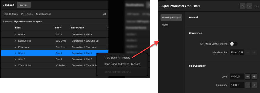
In each case, right-click on the source signal and select Show Signal Parameters to open the pop-up editor:

Levels can be adjusted from 0dB to -128 dB. The frequency for the two sine wave generators can be adjusted from 20Hz to 19998Hz (20kHz).